Power supply monitoring device of FPGA prototype verification system

A technology for power monitoring and prototype verification, applied in the modification of circuit devices, electrical components, power electronics, etc., can solve the problems of inconvenient movement of the power monitoring device, affecting the monitoring accuracy of the power monitoring device, affecting the normal operation of the power monitoring device, etc. , to achieve the effect of easy monitoring, improved mobility and low loss

Active Publication Date: 2021-02-19
SHANGHAI TECHN INST OF ELECTRONICS & INFORMATION
View PDF10 Cites 1 Cited by
  • Summary
  • Abstract
  • Description
  • Claims
  • Application Information

AI Technical Summary

Problems solved by technology

[0003] The FPGA prototype verification system is a hardware acceleration simulation verification platform based on FPGA technology, which can be used for chip prototype verification; the maximum number of FPGAs in the FPGA prototype verification system can be configured to 18, and power consumption has always been very high for FPGA prototype verification systems. Importantly, the appearance of the power monitoring device has improved the power consumption problem of the FPGA prototy

Method used


Image

  • Power supply monitoring device of FPGA prototype verification system
  • Power supply monitoring device of FPGA prototype verification system
  • Power supply monitoring device of FPGA prototype verification system

Examples


Embodiment Construction

[0019] The specific implementation manners of the present invention will be further described in detail below in conjunction with the accompanying drawings and embodiments. The following examples are used to illustrate the present invention, but are not intended to limit the scope of the present invention.

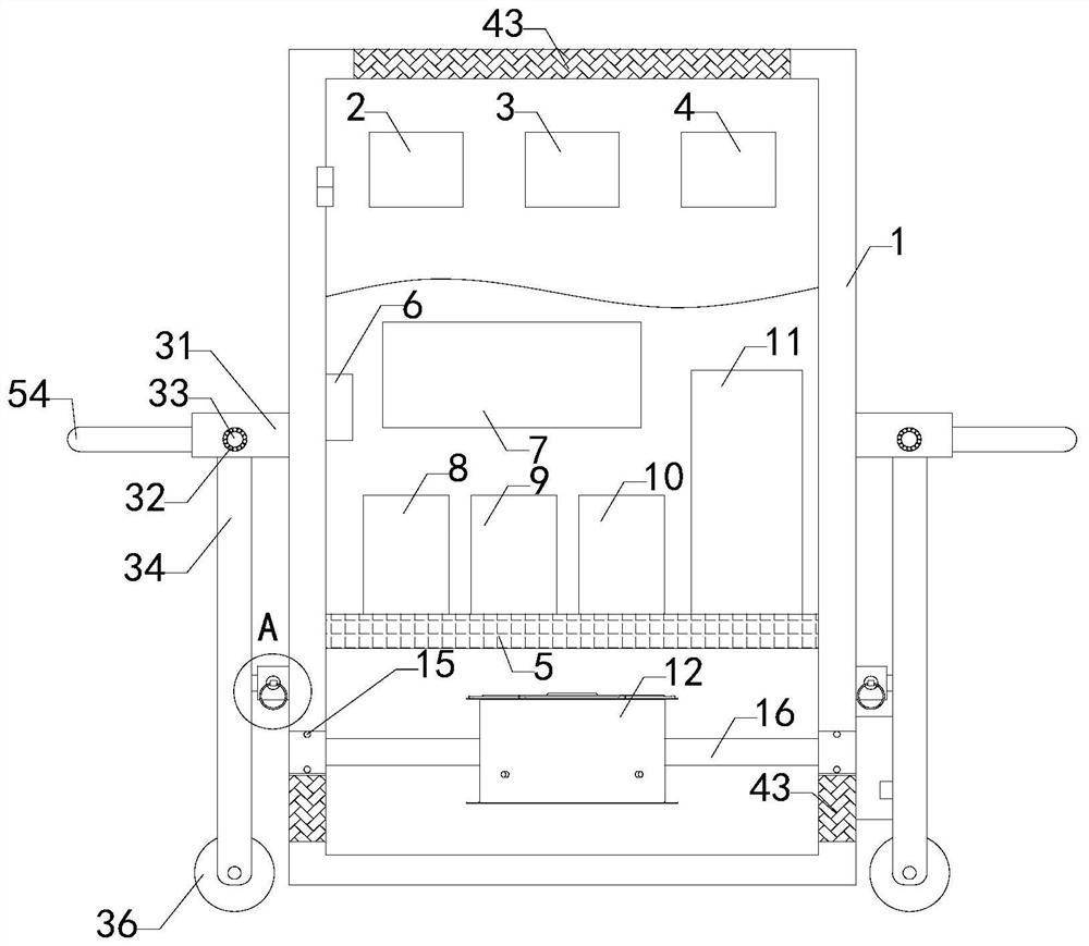
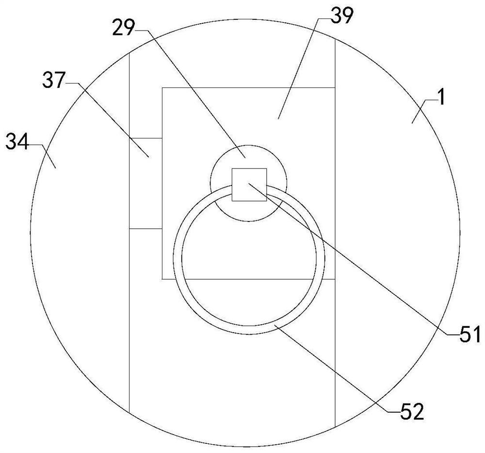
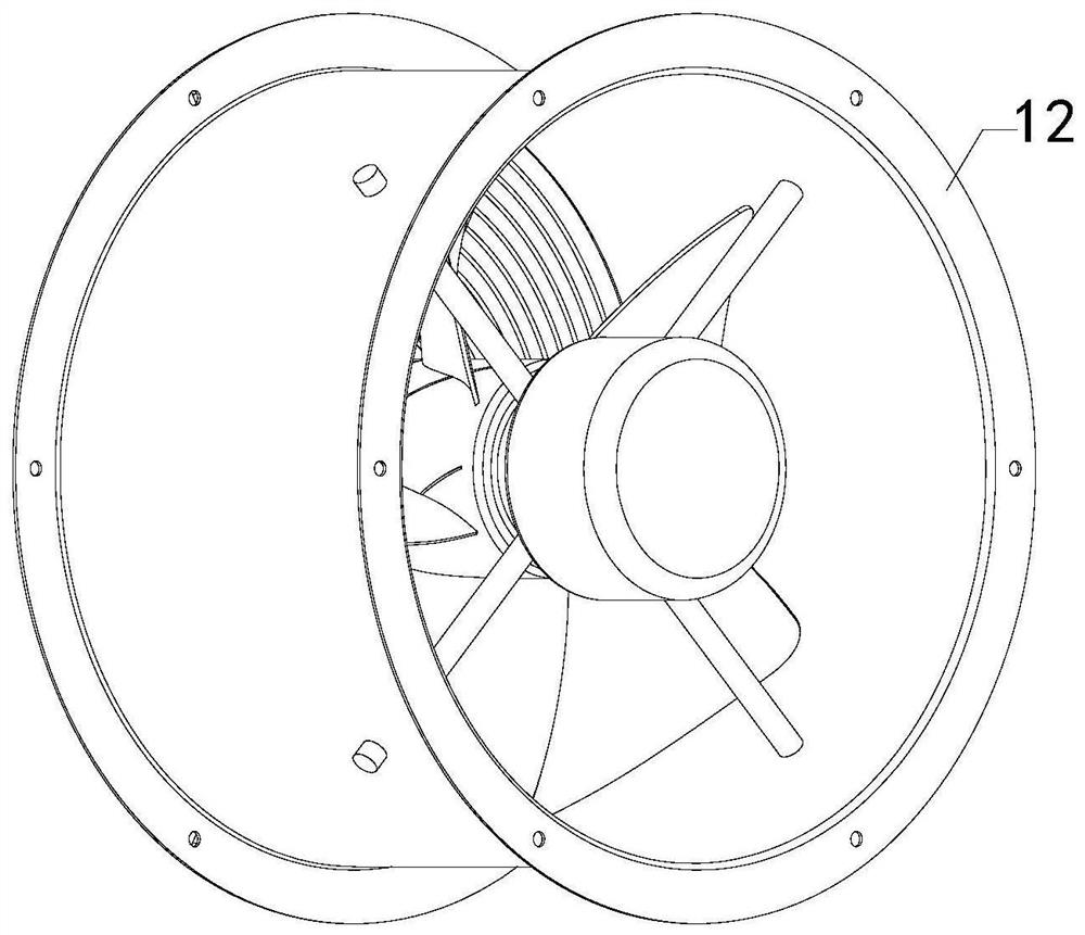
[0020] Such as Figure 1 to Figure 6As shown, the power monitoring device of a kind of FPGA prototype verification system of the present invention comprises shell 1, and output voltage display table 2, AC output voltage display table 3 and DC output voltage display table 4 are arranged on shell 1, and shell 1 interior is hollow , the inside of the shell 1 is provided with a hollow partition 5, on which a temperature detection device 6, a power supply device 7, a DC power distribution protector 8, an AC power distribution protector 9, a dual power converter 10 and a UPS are arranged. The main engine 11 also includes an axial flow fan 12, a reciprocating lead screw 13 and a...


PUM


Abstract

The invention relates to the technical field of FPGA accessory devices, in particular to a power supply monitoring device of an FPGA prototype verification system. The device is simple in structure, improves the heat dissipation performance and mobility of the power supply monitoring device, and reduces the use limitation. The device comprises a shell. An output voltage display meter, an alternating current output voltage display meter and a direct current output voltage display meter are arranged on the shell, the shell is hollow, a hollow partition plate is arranged in the shell, and a temperature detection device, a power supply device, a direct current distribution protector, an alternating current distribution protector, a dual-power converter and a UPS host are arranged on the partition plate. The device further comprises an axial flow fan, a reciprocating lead screw and a guide rod. First bearings are arranged in the lower half areas of the left side wall and the right side wallof the shell correspondingly, a left rotating shaft and a right rotating shaft are arranged at the left end and the right end of the axial flow fan correspondingly and connected with inner rings of the two sets of first bearings correspondingly, a box body is arranged on the right side wall of the shell, and the right end of the right rotating shaft extends into the box body. A gear is arranged at the right end of the right spindle.

Description

technical field [0001] The invention relates to the technical field of FPGA accessory devices, in particular to a power monitoring device of an FPGA prototype verification system. Background technique [0002] FPGA (Field Programmable Gate Array) is a product of further development on the basis of programmable devices such as PAL and GAL. It emerged as a semi-custom circuit in the field of application-specific integrated circuits (ASIC), which not only solves the shortcomings of custom circuits, but also overcomes the shortcomings of the limited number of original programmable device gates. [0003] The FPGA prototype verification system is a hardware acceleration simulation verification platform based on FPGA technology, which can be used for chip prototype verification; the maximum number of FPGAs in the FPGA prototype verification system can be configured to 18, and power consumption has always been very high for FPGA prototype verification systems. Importantly, the appe...

Claims


Application Information

Patent Timeline
IPC IPC(8): H05K7/20H05K5/02H02J13/00
CPCH05K7/20909H05K7/20145H05K7/20172H05K7/20209H05K7/20181H05K5/0217H05K5/0234H05K5/0213H02J13/00H02J13/00002
Inventor 祝周荣
Owner SHANGHAI TECHN INST OF ELECTRONICS & INFORMATION
Why Eureka
Try Eureka