Rectifier circuit, power source device, and method for driving rectifier circuit

A technology of a rectifier circuit and a driving method, which is applied in the directions of measuring devices, measuring current/voltage, high-efficiency power electronic conversion, etc., to achieve the effect of reducing transient currents

Pending Publication Date: 2021-02-19
SHARP KK
View PDF8 Cites 0 Cited by
  • Summary
  • Abstract
  • Description
  • Claims
  • Application Information

AI Technical Summary

Problems solved by technology

Transient currents create losses in the power supply circuit

Method used


Image

  • Rectifier circuit, power source device, and method for driving rectifier circuit
  • Rectifier circuit, power source device, and method for driving rectifier circuit
  • Rectifier circuit, power source device, and method for driving rectifier circuit

Examples


no. 1 approach 〕

[0029] Hereinafter, the rectifier circuit 1 of the first embodiment will be described. For convenience of description, members having the same functions as those described in the first embodiment are denoted by the same reference numerals in the subsequent embodiments, and description thereof will not be repeated.

[0030] (One purpose of rectification circuit 1)

[0031] As described above, a transient current flows through the rectifying element having the PN junction. On the other hand, as an example of a rectifier element made of a compound semiconductor that does not have a PN junction, SiC-SBD (Schottky Barrier Diode, Schottky barrier diode) or GaN-HEMT (High Electron Mobility Transistor, High Electron Mobility Transistor) are exemplified. mobility transistors), etc. In this rectifying element, no transient current originates from the PN junction.

[0032] However, there is a parasitic capacitance in this rectifying element. Therefore, when a voltage in a direction t...

no. 2 approach 〕

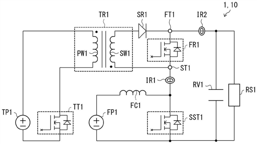
[0198] Figure 9 It is a figure which shows the power supply circuit 20 of 2nd Embodiment. The rectification circuit of the second embodiment is referred to as a rectification circuit 2 . In the rectification circuit 2, the power supply TP1 of the rectification circuit 1 is replaced with a power supply FP1. That is, in the power supply circuit 20 , the input power supply (power supply FP1 ) of the step-up chopper unit is also used as the power supply of the rectification circuit 2 . According to this configuration, the total number of power supplies of the power supply circuit 20 can be reduced, which is advantageous in terms of cost.

[0199] In addition, in the rectification circuit 2 , switching elements TT2 , TT3 , and TT4 are provided instead of the switching element TT1 of the rectification circuit 1 . The transformer of the rectification circuit 2 is called a transformer TR2 (Transformer). The primary winding and the secondary winding of the transformer TR2 are refe...

no. 3 approach 〕

[0209] Figure 10 It is a figure which shows the power supply circuit 30 of 3rd Embodiment. The rectification circuit of the third embodiment is referred to as a rectification circuit 3 . In the rectification circuit 3, the power supply TP1 of the rectification circuit 1 is replaced with a capacitor RV1. That is, the smoothing capacitor (capacitor RV1 ) of the step-up chopper unit can be used as the power source of the rectification circuit 3 . According to this configuration, since the total number of power supplies of the power supply circuit 30 can be reduced, it is advantageous in terms of cost.

[0210] In addition, in the rectification circuit 3 , switching elements TT5 , TT6 , and TT7 are provided instead of the switching element TT1 of the rectification circuit 1 . The transformer of the rectification circuit 3 is called a transformer TR3 (Transformer). The primary winding and the secondary winding of the transformer TR3 are referred to as primary winding PW3 and s...


PUM


Abstract

The objective of the present invention is to reduce a transient current effectively in a rectifier circuit. In a rectifier circuit (1), a first rectifying element (FR1) is provided between a first terminal (FT1) and a second terminal (ST1). In the rectifier circuit (1), a primary winding current flows from a power source (TP1) through a primary winding (PW1) of a transformer (TR1) when a switch element (TT1) is turned on. When the switch element (TT1) is turned off, a second rectifying element current flows from a secondary winding (SW1) of the transformer (TR1) through a second rectifying element (SR1). By causing the second rectifying element current to flow, a first reverse voltage, which is an instantaneous reverse voltage, is applied between the first terminal (FT1) and the second terminal (ST1).

Description

technical field [0001] The following disclosure relates to rectification circuits. Background technique [0002] A rectification element such as MOSFET (Metal Oxide Semiconductor Field Effect Transistor) or FRD (First Recovery Diode, fast recovery diode) is used in the rectification circuit provided in the power supply circuit. Such a rectifying element includes a diode having a PN junction. [0003] Therefore, when a voltage is applied to the rectifying element in the reverse direction, charges accumulated in the PN junction flow through the rectifying element as a transient current. This transient current is also called reverse recovery current. Transient currents create losses in the power supply circuit. [0004] Patent Documents 1 and 2 respectively disclose a circuit for the purpose of reducing the transient current. For example, in the circuit disclosed in Patent Document 1, in order to reduce the transient current, a diode and a transformer connected in parallel ...

Claims


Application Information

Patent Timeline
Patent Type & Authority Applications(China)
IPC IPC(8): H02M3/155
CPCH02M1/0051H02M1/342H02M3/158H02M3/33576H02M3/33592Y02B70/10G01R19/16538H02M1/0009H02M1/325H02M3/003H02M3/1584H02M7/217
Inventor 盐见竹史
Owner SHARP KK
Why Eureka
Try Eureka