
Horizontal screw centrifuge

A decanter centrifuge and isolation disc technology, applied in centrifuges, centrifuges with rotating drums, etc., can solve the problem of low solid content in the light phase, inability to separate solid particles in the liquid phase, and solid content in the light phase and other problems, to achieve the effect of saving the setting of the driving source

Pending Publication Date: 2021-02-23
JIANGSU JUNENG MASCH CO LTD
View PDF0 Cites 1 Cited by
  • Summary
  • Abstract
  • Description
  • Claims
  • Application Information

AI Technical Summary

Problems solved by technology

[0003] In view of the disadvantages that the existing equipment in the above-mentioned existing production cannot separate the smaller solid particles in the liquid phase, the solid content in the light phase is relatively high, and a post-treatment process is required for filtration, etc., the applicant provides a reasonable structure The decanter centrifuge enhances the processing capacity and effect of the equipment on materials containing finer particles, and finally obtains a light phase with low solid content, which can save space required for equipment, reduce investment and operating costs

Method used


Image

  • Horizontal screw centrifuge
  • Horizontal screw centrifuge
  • Horizontal screw centrifuge

Examples


Embodiment Construction

[0021] The specific implementation manner of the present invention will be described below in conjunction with the accompanying drawings.

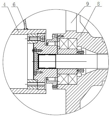
[0022] like image 3 Shown, decanter centrifuge of the present invention is in such as figure 1 On the basis of the existing decanter centrifuge shown, a disk system is added between the drum shell 5 and the inner pipe 4 near the light phase outlet 9 .

[0023] like Figure 4 As shown, the helical blade 6 at the end of the screw conveyor is near the side of the large end cap 8, and the isolation disc 14 of the disc system is arranged. The flow channel 13 is set on the side, and the flow channel 13 is a number of circular holes evenly distributed on the isolation plate 14. The light phase obtained by the decanter centrifuge enters the disc system through the flow channel 13 for secondary centrifugal separation. The other side of the isolation disc 14 has a gathering part 21 bent towards the direction of the large end cap 8. The gathering...


PUM


Abstract

The invention discloses a horizontal screw centrifuge. A spiral conveyor is located in a rotary drum shell, a feeding pipe is in communication with an inner pipe of the spiral conveyor, a dischargingport is formed in the inner pipe, spiral blades are fixed to the periphery of the inner pipe, a light phase outlet is located in an end cover on one side of the rotary drum shell, an isolation disc ofa disc system is arranged between the spiral blade at the tail end of the spiral conveyor and the light phase outlet, the isolation disc is fixed to the spiral conveyor, a flow channel is formed in the side, close to the inner pipe, of the isolation disc, and a solid phase channel is formed between the isolation disc and the inner wall of the rotary drum; and the disc system is positioned betweenthe isolation disc and the light phase outlet, and is fixed with the rotary drum. The disc system is additionally arranged between the rotary drum shell close to the light phase outlet and the innerpipe, tiny solid particles are rapidly separated from a liquid phase, the content of the tiny solid particles in a liquid is greatly reduced, and therefore final clear liquid with higher purity can beobtained, filtering treatment of the tiny solid particles does not need to be carried out in the later procedure, and the centrifuge capability of the centrifuge is increased.

Description

technical field [0001] The invention relates to the technical field of solid-liquid separation, in particular to a decanter centrifuge. Background technique [0002] The decanter centrifuge is a high-efficiency centrifugal equipment for solid-liquid separation, which can be used for the centrifugal treatment process of sludge generated in the process of industrial and civil sewage treatment. Compared with the belt filter press, the decanter centrifuge is due to its It has the characteristics of large processing capacity, automatic operation, and good dehydration effect, and has been widely used in the industrial field. figure 1 , figure 2 It is the structure of the existing decanter centrifuge, the drum includes a conical small end and a cylindrical large end, the small end and the large end are fixedly connected with the small end cover 2 and the large end cover 8 respectively, and the feed pipe 1 passes through The small end cap 2 communicates with the hollow inner tube...

Claims


Application Information

Patent Timeline
Patent Type & Authority Applications(China)
IPC IPC(8): B04B1/20B04B11/02B04B9/10B04B7/08B04B7/00
CPCB04B1/20B04B11/02B04B9/10B04B7/08B04B7/00
Inventor 牟宇慧牟富君王斌
Owner JIANGSU JUNENG MASCH CO LTD
Learn More