
Automatic material watching device and method under blast furnace trough

A blast furnace tank and blast furnace technology, applied to blast furnaces, blast furnace details, blast furnace parts, etc., can solve problems affecting the normal work of blast furnace operators, inaccurate judgment of raw and fuel quality, and affecting physical and mental health, so as to reduce the work of looking at materials, Good material effect, simple and reasonable structure

Inactive Publication Date: 2021-02-23
MAANSHAN IRON & STEEL CO LTD
View PDF8 Cites 0 Cited by
  • Summary
  • Abstract
  • Description
  • Claims
  • Application Information

AI Technical Summary

Problems solved by technology

[0003] During the daily inspection process of blast furnace operators, since the bottom of the blast furnace trough is far away from the central control room, it takes nearly 1 hour to look at the material under the trough each time, and under the condition of dark light at night, the quality of raw fuel The judgment is not accurate enough
Blast furnace ironmaking production is a continuous process. Too many times of checking materials seriously affects the normal work of blast furnace operators. The noisy and dusty environment under the tank also affects physical and mental health; Abnormal quality can easily lead to fluctuations in blast furnace conditions, especially in the case of large fluctuations in the quality of raw materials and fuels, replacement of materials in the silo, etc., or large fluctuations in blast furnace conditions. When it is necessary to know whether the raw material is abnormal, the effect of seeing the material under the tank is more prominent

Method used


Image

  • Automatic material watching device and method under blast furnace trough
  • Automatic material watching device and method under blast furnace trough

Examples


Embodiment 1

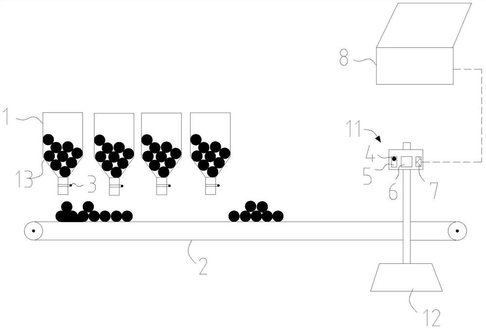
[0037] likefigure 1 As shown, the present invention is an automatic material viewing device under the blast furnace tank, and the blast furnace tank is provided with a furnace charge conveying belt 2 and a number of blast furnace raw material bins 1, and the blast furnace raw material bins 1 are arranged above the furnace charge conveying belt 2, and its innovation The advantage is that the automatic material viewing device under the blast furnace tank includes a computer 8 in the central control room, a material viewing component 11 and a number of signal emitting elements 3; When the gate of the blast furnace raw material bin 1 is opened, a signal is sent; the material viewing assembly 11 is fixedly arranged at the position behind each blast furnace raw material bin 1 above the furnace charge conveying belt 2, and is used for photographing the discharge of the blast furnace raw material bin 1 to the furnace charge conveyance The situation of the charge bar on the belt 2, whic...

Embodiment 2

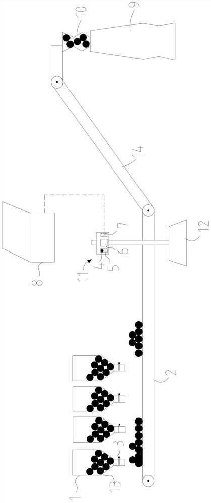
[0042] like figure 1 and figure 2 As shown, a method for checking material under a blast furnace tank of the present invention uses an automatic material checking device under a blast furnace tank described in Embodiment 1, and the furnace charge conveying belt 2 is connected with other conveying belts, and the furnace charge 13 is passed through The feeding equipment 10 is delivered to the blast furnace body 9, and the method of viewing the material is as follows:

[0043] Step 1. According to the material structure of the blast furnace, set the material type of each blast furnace raw material warehouse 1 and mark the information of each blast furnace raw material warehouse 1, and at the same time determine the discharge sequence of each blast furnace raw material warehouse 1 and the row of blast furnace raw material warehouse 1 to the furnace material conveyor belt 2. The furnace material bar on the top needs to see the position of the material;

[0044] Step 2. The opera...

Embodiment 3

[0055] Taking a certain blast furnace of a certain steel as an example, a kind of automatic material viewing device under the blast furnace trough described in Example 1 is used as an example, such as figure 1 and figure 2 As shown, there are 24 blast furnace raw material warehouses 1 in this embodiment, respectively labeled as 1-12A and 1-12B. The furnace charge conveying belt 2 is connected with other conveying belts 14, and the furnace charge 13 is sent through the feeding device 10. In the blast furnace body 9, the method of seeing material is as follows:

[0056] 1. According to the material structure of blast furnace: if ore includes sinter, pellet ore and raw ore, coke includes dry coke in new area and dry coke in old area, set the material type for 24 blast furnace raw material bins 1, and mark different blast furnace raw material bins 1 Charges used: such as 1-3A raw ore, 4-12A sintered ore, 1-5B new dry coke, 6-8B old dry coke, 9-12B pellets, and mark each blast fu...


PUM


Abstract

The invention discloses an automatic material watching device and method under a blast furnace trough. A furnace burden conveying belt and a plurality of blast furnace raw material bins are arranged under the blast furnace trough. The device comprises a central control room computer, a material watching assembly and a plurality of signal transmitting elements, wherein the blast furnace raw material bins are arranged above the furnace burden conveying belt; the signal transmitting elements are arranged at the positions of gates of the blast furnace raw material bins correspondingly; the material watching assembly is fixed to the position, above the furnace burden conveying belt, behind the blast furnace raw material bins and comprises a signal receiving element, a controller, a shooting device and a data transmission device; the signal receiving element is in communication connection with the signal transmitting elements; the signal receiving element, the shooting device and the data transmission device are connected with the controller; and the central control room computer is connected with the data transmission device. By applying the automatic material watching device and method, operators can conduct automatic material watching and online material watching under the trough at any time, the material watching effect is good, contrastive analysis can also be conducted, and thesignificance is more prominent when the raw fuel quality or material discharging abnormity and furnace condition fluctuation need to be watched in time.

Description

technical field [0001] The invention belongs to the technical field of blast furnace ironmaking equipment, and more specifically relates to an automatic material checking device and a material checking method under a blast furnace tank. Background technique [0002] Blast furnace operation emphasizes "seven points of raw materials and three points of operation". The quality of blast furnace raw fuel has a direct and important impact on its furnace stability, productivity, and fuel consumption. Therefore, in the blast furnace operation, looking at the material under the tank is the daily and important work of the blast furnace operators. The material under the trough is mainly to observe the physical characteristics of the material such as color, particle size, and moisture at the position of the material conveying belt, and judge the quality change of the raw material and fuel through observation, so as to provide a basic judgment for the operation of the blast furnace. abn...

Claims


Application Information

Patent Timeline
IPC IPC(8): B65G43/08B65G47/18C21B7/00
CPCB65G43/08B65G47/18C21B7/00
Inventor 吴宏亮郭其飞
Owner MAANSHAN IRON & STEEL CO LTD
Learn More