Hollow part electroplating device

An electroplating device and parts technology, applied in the direction of electrodes, electrolytic process, electrolytic components, etc., can solve the problem that the inner and outer circular surfaces of the bearing ring cannot be electroplated at the same time, the bearing ring is not effectively limited, and the quality of the inner circular surface plating is poor influence and other issues, to achieve the effect of improving electroplating efficiency, ensuring electroplating quality, and good electroplating effect

Pending Publication Date: 2021-02-23
CHINA HANGFA GUIZHOU LIYANG AVIATION POWER CO LTD
View PDF6 Cites 2 Cited by
  • Summary
  • Abstract
  • Description
  • Claims
  • Application Information

AI Technical Summary

Problems solved by technology

[0004] However, before electroplating, it is necessary to stack the bearing rings one by one in the sleeve, then install the sleeve on the gland, insert the electrode rod into the sleeve, and finally place the fixture in the copper electroplating solution tank to start electroplating , After the electroplating is completed, the above steps are reversely completed to remove the bearing ring from the sleeve, and the electroplating efficiency is low
In addition, the bearing ring is not effectively limited. For example, if the outer circle of the bearing ring is positioned through the sleeve, since the outer circle of the bearing ring is in contact with the inner wall of the sleeve, there will be an inner and outer circular surface of the bearing ring. The problem that electroplating cannot be performed at the same time; if the outer diameter of the bearing ring is smaller than the inner diameter of the sleeve, the bearing ring will be dislocated due to the lack of effective limit, and the inner circular surface of some bearing rings will contact the electrode rod, giving the inner The quality of round surface plating is badly affected

Method used


Image

  • Hollow part electroplating device
  • Hollow part electroplating device

Examples


Embodiment Construction

[0022] The technical solution of the present invention is further described below, but the scope of protection is not limited to the description.

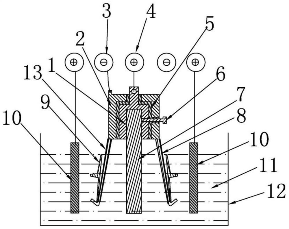
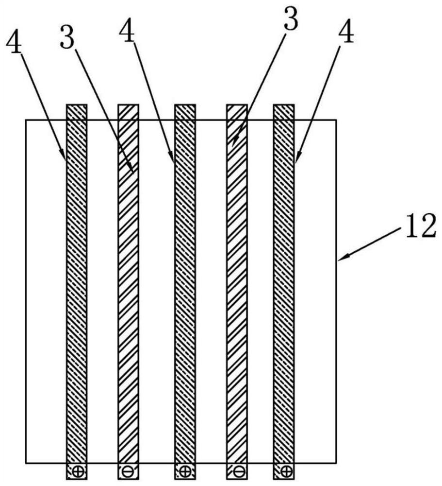
[0023] Such as figure 1 and figure 2 As shown, a hollow part electroplating device according to the present invention includes an electroplating tank 12, an anode assembly and a cathode assembly, and a plurality of anode rods 4 are arranged side by side above the electroplating tank 12, and above the electroplating tank 12 is A cathode rod 3 is arranged between two adjacent anode rods 4, and the cathode assembly is used to place a hollow part 9. The anode assembly and the cathode assembly are detachably connected, and are located on the inside of the cathode assembly. Insulation is maintained between them, the cathode assembly is electrically connected to the cathode rod 3 , and the anode assembly is electrically connected to the anode rod 4 . When in use, the anode rod 4 and the cathode rod 3 are electrically connected to the p...


PUM


Abstract

The invention discloses a hollow part electroplating device which belongs to the technical field of electroplating. The device comprises an electroplating slot, an anode assembly and a cathode assembly, wherein a plurality of anode rods which are arranged side by side are arranged above the electroplating slot; a cathode anode is arranged between adjacent two anode rods above the electroplating slot; the cathode assembly is used for placing a hollow part; the anode assembly is detachably connected to the cathode assembly and is positioned at the inner side of the cathode assembly; the anode assembly and the cathode assembly are kept insulated; the cathode assembly is electrically connected to the cathode rods; and the anode assembly is electrically connected to the anode rods. In an electroplating process, the anode rods are mounted inside the hollow part, and anode plates are mounted outside the hollow part, so that inner and outer surfaces of the hollow part are good in electroplating effect and are high in electroplating efficiency. The hollow part is supported by a hanger, so that the hollow part can be effectively limited, placed and taken, and thus, electroplating efficiencyis favorably improved.

Description

technical field [0001] The invention relates to an electroplating device for hollow parts, belonging to the technical field of electroplating. Background technique [0002] At present, in the electroplating of parts, some parts are cavity parts. Using the traditional electroplating method, because the inner surface of the cavity of the part needs to be electroplated, it needs to absorb the metal ions in the electroplating bath, and the flow speed of the electroplating bath is difficult to reach the level of electroplating. The speed required results in poor plating on the inner surface of the cavity of the part. [0003] The Chinese patent document with the publication number CN202830208U discloses a jig for electroplating copper on the inner surface of bearing rings. During the production process of electroplating copper, the bearing rings are stacked one by one in the sleeve, and the end faces with the same width need to be opposite to each other. Stacking: If the big end...

Claims


Application Information

Patent Timeline
Patent Type & Authority Applications(China)
IPC IPC(8): C25D17/00C25D7/04C25D17/06C25D17/12
CPCC25D17/00C25D7/04C25D17/06C25D17/12
Inventor 李红涂喜峰罗定莉刘胜愷邱伦厚
Owner CHINA HANGFA GUIZHOU LIYANG AVIATION POWER CO LTD
Why Eureka
Try Eureka