

Anti-impact coal mine supporting frame and using method
An anti-shock and coal mine technology, which is applied in mine roof support, mining equipment, earthwork drilling and mining, etc., can solve problems such as insufficient buffering, poor impact mitigation effect, underground damage, etc. effect of sufficiency
- Summary
- Abstract
- Description
- Claims
- Application Information
AI Technical Summary
Problems solved by technology
Method used
Image

Examples
Embodiment 1
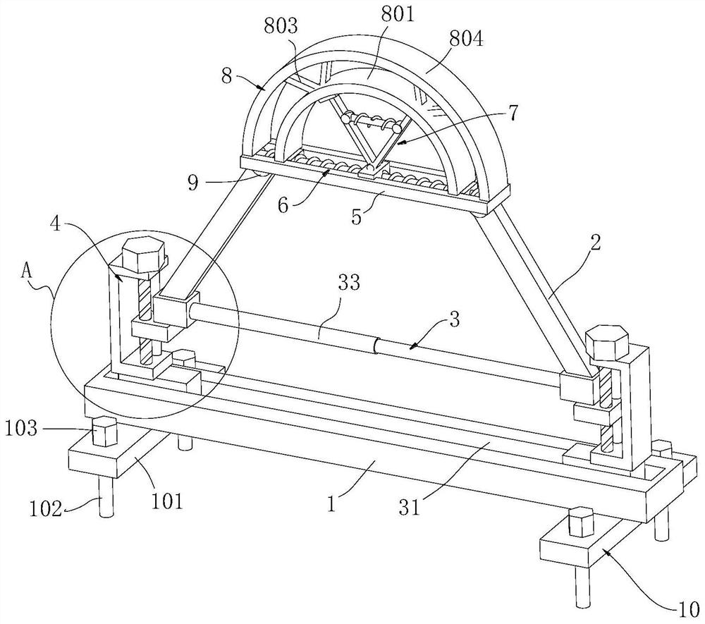
[0040] Example 1, please refer to Figure 1-3 and Figure 5 , this embodiment provides a technical solution: an anti-shock coal mine support frame, including a bottom bar 1, a diagonal brace 2, a diagonal brace angle adjustment unit 3, a diagonal brace height adjustment unit 4, a push rod 5, Horizontal buffer unit 6, vertical buffer unit 7 and top support unit 8;
[0041] The top of the bottom rod 1 is equipped with two diagonal brace height adjustment units 4 through the diagonal brace angle adjustment unit 3, and the bottom sides of the top rod 5 are respectively connected to the tops of the two diagonal braces 2 through hinge supports 9. The top of the bar 5 is equipped with a top support unit 8 through the horizontal buffer unit 6, and a vertical buffer unit 7 is installed between the inner side of the top support unit 8 and the horizontal buffer unit 6;
[0042] The diagonal brace angle adjustment unit 3 includes a strip groove 31, a slide block 32, a hydraulic expansio...
Embodiment 2
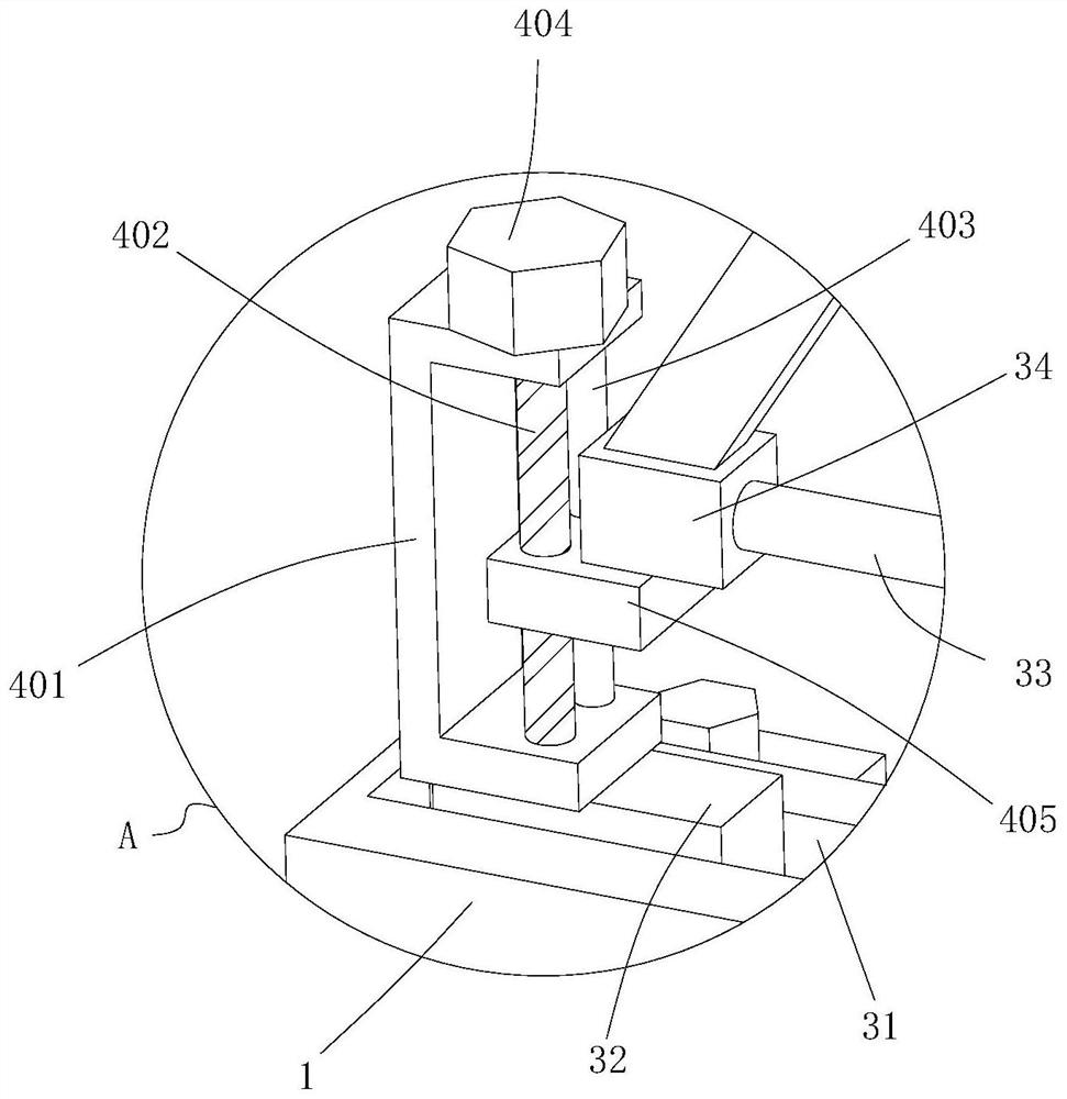
[0058] Example 2, please refer to Figure 4 , this embodiment provides a technical solution: an anti-shock coal mine support frame, the structure of this embodiment is roughly the same as that of Embodiment 1, the difference is that the diagonal brace height adjustment unit 4 includes a U-shaped frame 411, Vertical groove 412, vertical slide block 413, hydraulic cylinder 414 and movable block two 415, the bottom of U-shaped frame 411 is fixed on slide block one 32, and the inboard of U-shaped frame 411 offers vertical vertical groove 412, and U-shaped frame 411 The inner bottom of the inner side is fixedly connected to the bottom of the hydraulic cylinder 414, the top of the hydraulic cylinder 414 is fixed with a movable block 2 415, and the side of the movable block 2 415 is fixed with a vertical slider 413, and the vertical slider 413 is slidably connected with the vertical groove 412, and the movable block The side of two 415 is fixed with adjustment seat 34.
[0059] The ...
Embodiment 3
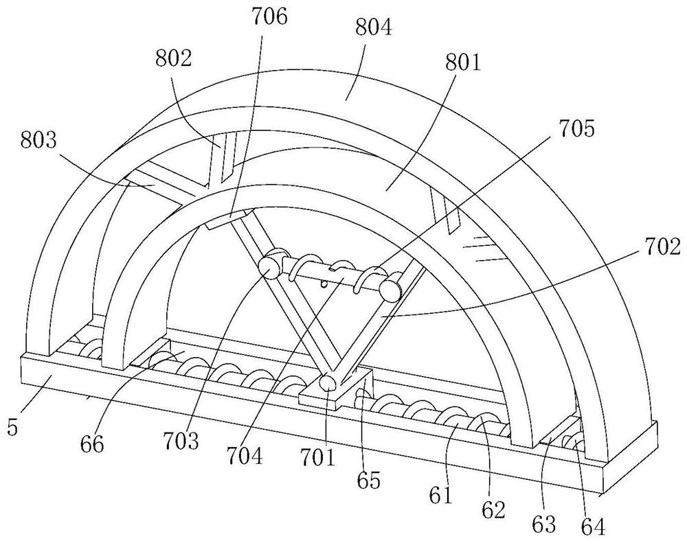
[0060] Embodiment three, please refer to Figure 6, this embodiment provides a technical solution: an anti-shock coal mine support frame, the structure of this embodiment is roughly the same as that of Embodiment 1, the difference is that the vertical buffer unit 7 includes a mounting plate 711 and a support block 712 , vertical rod 713, mounting column 714, side support 715, cross bar 716, center block 717, movable connection seat 718, cylinder body 719, end block 720, movable pillar 721, extension spring 2 722 and middle spring 723, install The plate 711 is fixed on the top of the partition block 65, and the two ends of the top of the mounting plate 711 are movably connected to the bottom ends of the two vertical rods 713 respectively through the support blocks 712, and the inner sides of the top of the two vertical rods 713 are respectively movably connected to side supports 715, The sides of the two side supports 715 are respectively fixedly connected to one end of the two...
PUM
 Abstract
Description
Claims
Application Information