
Furnace-entering firing device with high use efficiency

A high-efficiency, furnace-feeding technology, used in furnaces, furnace types, furnace components, etc., can solve problems such as the limit of objects that cannot be processed by the grinding wheel, damage to the processed objects of the grinding wheel, trouble, etc. The effect of stability

Inactive Publication Date: 2021-02-23
芜湖市华峰砂轮有限公司
View PDF0 Cites 2 Cited by
  • Summary
  • Abstract
  • Description
  • Claims
  • Application Information

AI Technical Summary

Problems solved by technology

[0005] The purpose of the present invention is to provide a high-efficiency furnace firing device to solve the problem that the existing grinding wheel processing plant in the background technology cannot quickly select the type of different grinding wheel materials during the process of using the furnace firing device. Size and quantity, adjust the height of the rack at any time, and need to reassemble different types of racks, causing certain troubles, and at the same time cannot limit the position of the grinding wheel processing, and it is very easy to burn due to vibration during the moving process. The problem of damage to the processed grinding wheel

Method used


Image

  • Furnace-entering firing device with high use efficiency
  • Furnace-entering firing device with high use efficiency
  • Furnace-entering firing device with high use efficiency

Examples


Embodiment Construction

[0036] The following will clearly and completely describe the technical solutions in the embodiments of the present invention with reference to the accompanying drawings in the embodiments of the present invention. Obviously, the described embodiments are only some, not all, embodiments of the present invention.

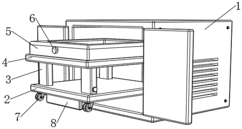
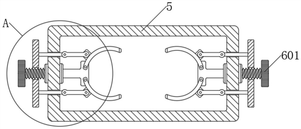
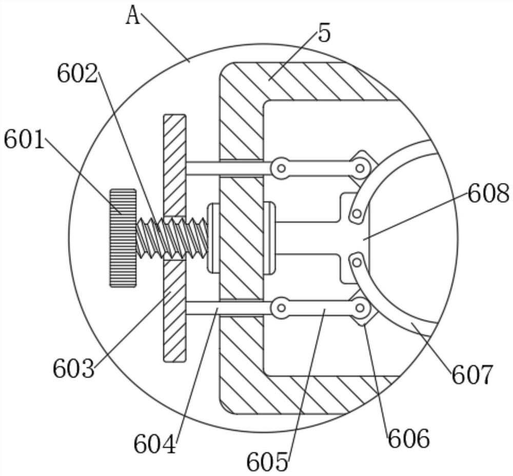
[0037] see Figure 1 to Figure 11, an embodiment provided by the present invention: a high-efficiency furnace firing device, including a cabinet body 1, a bottom plate 2, a support structure 3, a lower plate 301, a rotating shaft 302, a No. 1 helical gear 303, a No. 2 Helical gear 304, threaded rod 305, upper plate 306, slide rod 307, shock absorbing structure 4, shock absorbing box 401, fixed block 402, No. 1 spring 403, No. 1 ear seat 404, telescopic guide rod 405, No. 2 ear seat 406, installation box 5, limit mechanism 6, knob 601, screw rod 602, installation block 603, No. 1 connecting rod 604, No. 2 connecting rod 605, connecting block 606, arc clamping rod 607,...


PUM


Abstract

The invention discloses a furnace-entering firing device with high use efficiency. The furnace-entering firing device comprises a cabinet body, wherein a bottom plate is arranged inside the cabinet body; supporting structures are fixedly arranged at four end corners of the upper end surface of each supporting structure; a damping structure is fixedly arranged on the upper end surfaces of the foursupporting structures; the upper end surface of the damping structure is connected with a mounting box in a sliding mode; limiting mechanisms are arranged at the front end and the rear end of the mounting box; pulleys are fixedly arranged at four end corners of the lower end surface of the bottom plate; positioning mechanisms are arranged inside two pulleys; and a brake mechanism is arranged on the front side edge of each pulley. The furnace-entering firing device with high use efficiency is simple in structure, convenient to operate and convenient to use, can be used for fixing and limiting grinding wheel materials needing to be fired, so that the grinding wheel materials needing to be fired are prevented from generating displacement in the firing process; and meanwhile, the device can besupported, is convenient to move, is relatively high in stability, is convenient for regulating height of the mounting box according to needs, and has a damping function.

Description

technical field [0001] The invention relates to the technical field of grinding wheel firing, in particular to a furnace firing device with high use efficiency. Background technique [0002] With the rapid development of social economy, pottery refers to clay as the tire, which is processed and formed by hand kneading, wheel making, molding and other methods, and then baked at a high temperature of about 1000-1200 degrees. According to the order, it can be divided into four major processes: raw material processing (including mud and glaze), mud molding, glaze and calcination. The production of Chinese pottery has a long history of more than 11,700 years. The most critical process of making pottery is One process is firing in a kiln. In a pottery kiln, the high temperatures generated by the wood fuel cause the clay to chemically react, resulting in changes in the composition, properties and color of the body. [0003] However, in the process of using the furnace firing devi...

Claims


Application Information

Patent Timeline
Patent Type & Authority Applications(China)
IPC IPC(8): F27B17/00F27D3/12F27D5/00
CPCF27B17/0016F27D3/123F27D5/0006F27D2005/0081
Inventor 吴宏灯孙述刚
Owner 芜湖市华峰砂轮有限公司
Learn More