Heterogeneously integrated thermal infrared sensing element and thermal infrared sensor

A technology of heterogeneous integration and sensing elements, applied in the direction of electric radiation detectors, instruments, measuring devices, etc., can solve the trouble of making array elements and the inability to configure circuits, etc.

Inactive Publication Date: 2021-02-23
李美燕
View PDF1 Cites 0 Cited by
  • Summary
  • Abstract
  • Description
  • Claims
  • Application Information

AI Technical Summary

Problems solved by technology

The disadvantage of this method is that there is no way to configure the circuit under the cavity. This technology is more troublesome when making array elements, because the circuit can only be placed next to the thermopile, so that the fill factor (fill) of each pixel (pixel) factor (referr

Method used


Image

  • Heterogeneously integrated thermal infrared sensing element and thermal infrared sensor
  • Heterogeneously integrated thermal infrared sensing element and thermal infrared sensor
  • Heterogeneously integrated thermal infrared sensing element and thermal infrared sensor

Examples


Embodiment Construction

[0034] In order to make the above content of the present invention more comprehensible, preferred embodiments are specifically cited below, together with the accompanying drawings, and described in detail as follows.

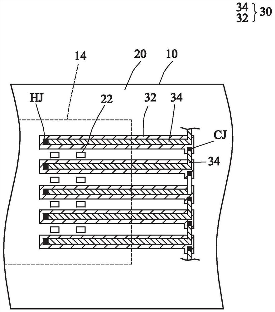
[0035] The spirit of the present invention is to use the technology of heterogeneous integration, first use the integrated circuit (especially CMOS) front-end process to form a circuit (including multiple metal layers) in the wafer, and then define the circuit on the wafer in the back-end process. A groove or cavity or predetermined sacrificial layer structure. Then use wafer bonding technology to bond the two wafers together, and then perform material removal, patterning and wiring processes to manufacture thermal infrared sensing elements or thermal infrared sensors (array elements).

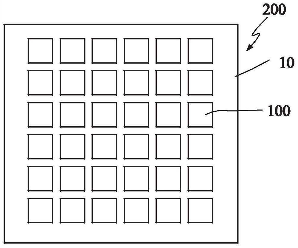
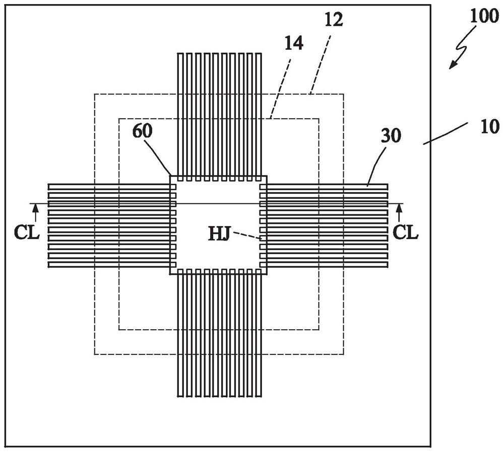
[0036] Figure 1A A schematic top view of a thermal infrared sensor according to a preferred embodiment of the present invention is shown. Such as Figure 1A As shown, a therma...


PUM


Abstract

A heterogeneously integrated thermal infrared sensing element includes: a substrate; the sensing circuit that is positioned in or on the substrate; the cavity that is located in or on the substrate, and the sensing circuit is located below the cavity; the thermocouple that is made of a material which is manufactured on the second substrate and transferred above the cavity in a bonding mode, the thermocouple comprises a first conductor and a second conductor, the first ends of the first conductor and the second conductor of the thermocouple are connected to a hot end located above the cavity, and the second end of the first conductor and the second conductor of the thermocouple are connected to a hot end located above the cavity; the second ends of the first conductor and the second conductor of the thermocouple are cold ends arranged at the edge of the cavity and are electrically connected to the sensing circuit.

Description

technical field [0001] The present invention relates to a thermal infrared sensing element and a thermal infrared sensor, and in particular to a heterogeneously integrated thermal infrared sensing element and a thermal infrared sensor. Background technique [0002] In recent years, thermal infrared sensing elements such as thermocouples are often used for temperature measurement. The principle is to make the hot end and the cold end (the other end between the conductors) Junction) to generate a temperature difference to generate a diffusion current. In order to eliminate this current spread, the thermocouple must provide a considerable reverse electromotive force, which is the Seedback voltage. By measuring the Seebeck voltage, the temperature difference between the two ends of the thermocouple can be known to correct the temperature. The Seebeck voltage is determined by the product of the temperature difference between the two ends and the Seebeck coefficient of the two c...

Claims


Application Information

Patent Timeline
IPC IPC(8): G01J5/12
CPCG01J5/12G01J2005/123
Inventor 周正三
Owner 李美燕
Why Eureka
Try Eureka