
Ultra-wideband beam splitting and combining device

A beam combiner and ultra-broadband technology, applied in the direction of instruments, optical waveguide coupling, light guide, etc., can solve the problems of low transmission efficiency, difficulty in large-scale integration, and high manufacturing precision requirements

Pending Publication Date: 2021-02-23
WUHAN OPTICAL VALLEY INFORMATION OPTOELECTRONICS INNOVATION CENT CO LTD +1
View PDF8 Cites 0 Cited by
  • Summary
  • Abstract
  • Description
  • Claims
  • Application Information

AI Technical Summary

Problems solved by technology

[0003] However, the existing 3dB beam splitters have the disadvantages of high manufacturing precision, long waveguide length, low transmission efficiency, and difficulty in large-scale integration.

Method used


Image

  • Ultra-wideband beam splitting and combining device
  • Ultra-wideband beam splitting and combining device
  • Ultra-wideband beam splitting and combining device

Examples


preparation example Construction

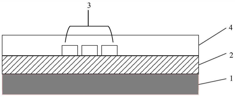
[0073] The embodiment of the present invention also provides a preparation method of an ultra-broadband beam splitter and combiner. For details, see Figure 5 . As shown in the figure, it includes the following steps:

[0074] Step 501, providing a substrate;

[0075] Step 502, forming a first waveguide layer on the substrate;

[0076] Step 503, directly forming a second waveguide layer on the first waveguide layer, wherein the second waveguide layer includes an input tapered waveguide region and an output tapered waveguide region for optical signal coupling;

[0077] Wherein, the first projection of the input graded waveguide region in the direction perpendicular to the substrate, the second projection of the output graded waveguide region in the direction perpendicular to the substrate, and the first waveguide layer A third projection in a direction perpendicular to the substrate satisfies the following relationship: the first projection and the second projection complete...


PUM

PropertyMeasurementUnit
Thicknessaaaaaaaaaa

Abstract

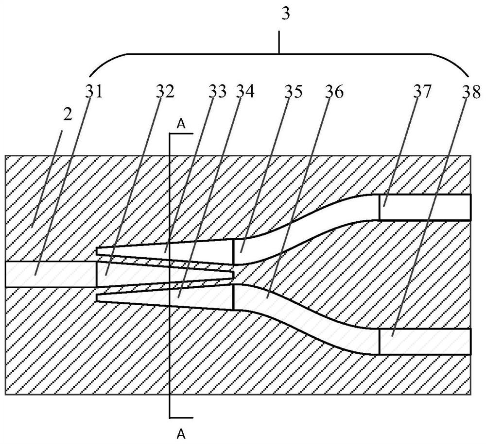
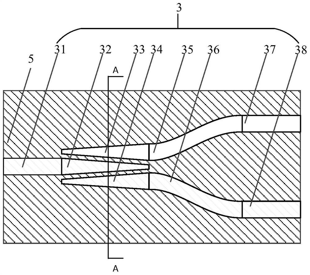
The embodiment of the invention discloses an ultra-wideband beam splitting and combining device. The device comprises a substrate, and a first waveguide layer and a second waveguide layer which are stacked on the substrate in sequence. The upper surface of the first waveguide layer is in direct contact with the lower surface of the second waveguide layer. The second waveguide layer comprises an input gradual change waveguide region and an output gradual change waveguide region which are used for carrying out optical signal coupling. A first projection of the input gradual change waveguide region in the direction perpendicular to the substrate, a second projection of the output gradual change waveguide region in the direction perpendicular to the substrate and a third projection of the first waveguide layer in the direction perpendicular to the substrate meet the relation that the first projection and the second projection completely fall into the range of the third projection.

Description

technical field [0001] The invention relates to the field of optical communication devices, in particular to an ultra-wideband beam splitter and combiner. Background technique [0002] The ultra-wideband 3dB (decibel) beam combiner is a crucial device in optical communication systems, and is widely used in optical switches, optical modulators and multiplexing / demultiplexing devices. [0003] However, the existing 3dB beam splitters have the disadvantages of high manufacturing precision requirements, too long waveguide length, low transmission efficiency, and difficulty in large-scale integration. Contents of the invention [0004] In view of this, embodiments of the present invention provide an ultra-wideband beam splitter and combiner to solve at least one problem existing in the background art. [0005] In order to achieve the above object, the technical solution of the present invention is achieved in that: [0006] On the one hand, an embodiment of the present invent...

Claims


Application Information

Patent Timeline
IPC IPC(8): G02B6/122G02B6/12G02B6/26
CPCG02B6/122G02B6/1228G02B6/12G02B6/26G02B2006/12147G02B2006/12061Y02D30/70
Inventor 张宇光肖希王磊陈代高李淼峰胡晓冯朋
Owner WUHAN OPTICAL VALLEY INFORMATION OPTOELECTRONICS INNOVATION CENT CO LTD
Learn More