
High-power lateral pumping active optical fiber

A high-power, pumping technology, applied in the field of high-power laterally pumped active fibers, can solve the problems of high power and pumping difficulty, fiber fusion, cutting and splicing difficulties, and manufacturing difficulties, etc., and achieve particle number inversion. The effect of turning the level uniformly, reducing the mode instability problem, and improving the light-to-light conversion efficiency

Pending Publication Date: 2022-04-08
WUHAN BRIGHTCORE OPTICAL FIBER CO LTD
View PDF3 Cites 1 Cited by
  • Summary
  • Abstract
  • Description
  • Claims
  • Application Information

AI Technical Summary

Problems solved by technology

At present, people generally use double-clad fibers with large mode field area to increase the output power of fiber lasers. A pump beam combiner is needed to inject pump light into the active fiber, but the manufacturing process of the pump beam combiner is difficult. High, high cost, low carrying power, short coupling distance of side-pumped beam combiner, and low coupling efficiency. Welding, cutting and splicing bring difficulties
[0004] In order to solve the problem of high power and high difficulty of pumping, as well as the problem of axial unevenness of pump absorption, CN101038353A proposes to use multi-core optical fiber to pump separately, but the increase in the number of fiber cores cannot improve the performance of a single fiber. The power of the core, and at the same time bring great challenges to the coupling of the core
U.S. Patent US 6826335 B1 adopts the side pumping method, and the pump fiber and the active fiber are coupled by side welding at a certain angle, but the essence is device manufacturing, which is difficult to manufacture, high in cost, and low in coupling efficiency

Method used


Image

  • High-power lateral pumping active optical fiber
  • High-power lateral pumping active optical fiber
  • High-power lateral pumping active optical fiber

Examples


Embodiment Construction

[0028] In order to make the purpose, technical solutions and advantages of the embodiments of the present invention clearer, the technical solutions in the embodiments of the present invention are clearly and completely described below. Obviously, the described embodiments are part of the embodiments of the present invention, not all Example. Based on the embodiments of the present invention, all other embodiments obtained by persons of ordinary skill in the art without making creative efforts belong to the protection scope of the present invention.

[0029] Unless otherwise specified, all materials used in the examples of the present invention are commercially available.

[0030] If not specified, the technical means used in the embodiments of the present invention are conventional means well known to those skilled in the art.

[0031] In order to facilitate the understanding of the present invention, at first the professional terms involved in the present invention are coll...


PUM

PropertyMeasurementUnit
diameteraaaaaaaaaa
diameteraaaaaaaaaa
elastic modulusaaaaaaaaaa

Abstract

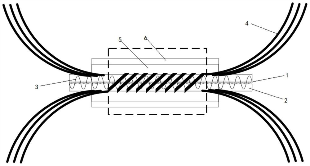
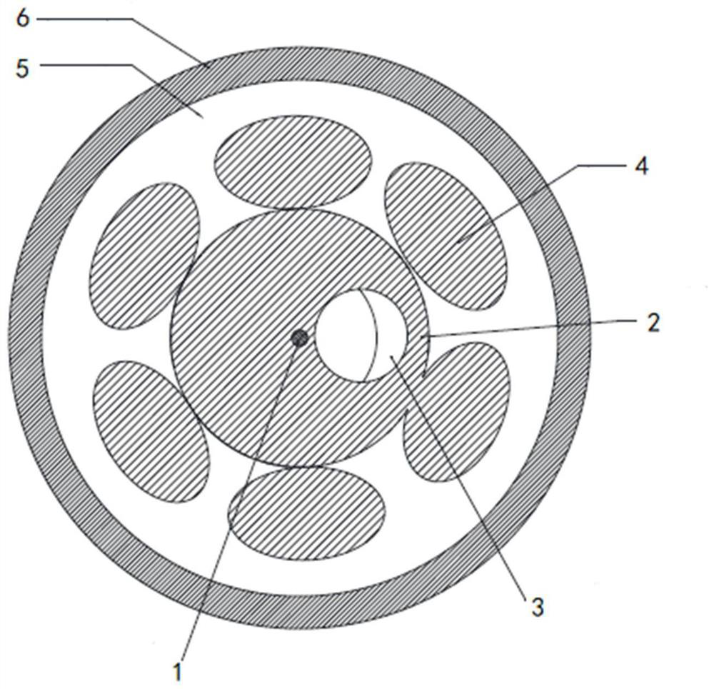
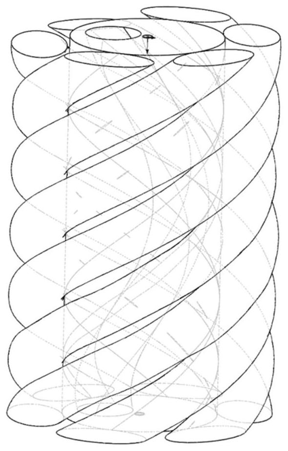
The invention provides a high-power lateral pumping active optical fiber which comprises a pumping coupling area with a certain length, the pumping coupling area comprises a fiber core, a quartz cladding, a pumping coupling fiber core, a low-refractive-index coating and a high-refractive-index coating from inside to outside, a low-refractive-index winding cladding is arranged in the quartz cladding, and a high-refractive-index winding cladding is arranged in the high-refractive-index coating. The low-refractive-index winding wrapping layer is wound around the fiber core with the fiber core as the axis and spaced from the fiber core by a certain distance, the pumping coupling fiber core is periodically and tightly wound outside the quartz wrapping layer, and the quartz wrapping layer and the pumping coupling fiber core are completely wrapped by the low-refractive-index coating. The low-refractive-index winding cladding and the pumping coupling fiber core which are periodically wound are introduced into the active optical fiber structure, the pumping coupling efficiency can be effectively improved, the nonlinearity and TMI effect can be reduced, the number of devices in a laser or an amplifier can be reduced, the cost can be reduced, the reliability of the whole machine can be improved, and the problem of high-efficiency integration of the active optical fiber pumping can be solved.

Description

technical field [0001] The invention relates to the technical field of active optical fibers, in particular to a high-power side-pumped active optical fiber. Background technique [0002] Fiber laser is a laser that uses optical fiber as the fiber medium. Fiber laser has become one of the mainstream lasers in the field of laser applications due to its high conversion efficiency, good heat dissipation performance and stability. [0003] With the continuous expansion of laser application fields, users have higher and higher demands on the output power of fiber lasers. At present, people generally use double-clad fibers with large mode field area to increase the output power of fiber lasers. A pump beam combiner is needed to inject pump light into the active fiber, but the manufacturing process of the pump beam combiner is difficult. High, high cost, low carrying power, short coupling distance of side-pumped beam combiner, and low coupling efficiency. Welding and cutting join...

Claims


Application Information

Patent Timeline
Patent Type & Authority Applications(China)
IPC IPC(8): H01S3/067
Inventor 莫琦姜佳包箭华张旭韩圆李云丽陈靖肖光
Owner WUHAN BRIGHTCORE OPTICAL FIBER CO LTD
Learn More