Machined part surface vibration line defect detection method

A defect detection and parts technology, applied in computer parts, instruments, design optimization/simulation, etc., can solve problems such as low detection accuracy of surface chattering defects and parameter drift of flutter detection model, and achieve the effect of improving accuracy

Pending Publication Date: 2021-02-23
HUAZHONG UNIV OF SCI & TECH +1
View PDF0 Cites 3 Cited by
  • Summary
  • Abstract
  • Description
  • Claims
  • Application Information

AI Technical Summary

Problems solved by technology

[0004] Aiming at the above defects or improvement needs of the prior art, the present invention provides a method for detecting chattering defects on the machined surface, the purpose of which is to solve the problem of chatter detection models occurring in the prior art due to the removal of workpiece material and tool wear during the machining process. Parameter drift, which leads to the technical problem of low detection accuracy of surface vibration defects

Method used


Image

  • Machined part surface vibration line defect detection method
  • Machined part surface vibration line defect detection method
  • Machined part surface vibration line defect detection method

Examples


Embodiment 1

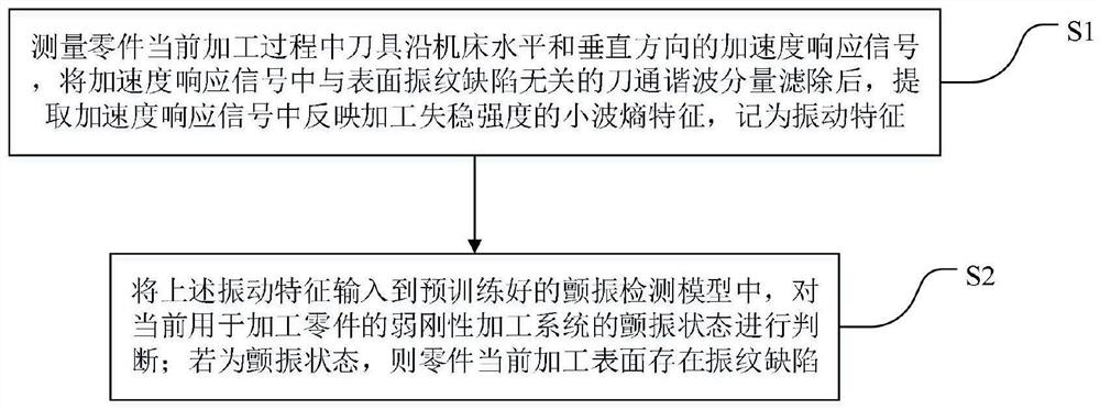
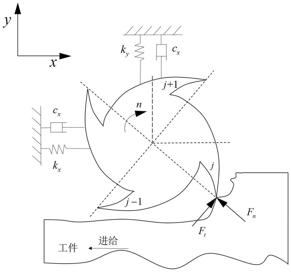
[0031] A method for detecting vibration marks on the surface of a machined part, such as figure 1 shown, including the following steps:

[0032] S1. Measure the acceleration response signal of the tool along the horizontal and vertical directions of the machine tool during the current processing of the part, filter out the tool pass harmonic component in the acceleration response signal that is not related to the surface vibration defect, and extract the processing instability reflected in the acceleration response signal The wavelet entropy feature of intensity is denoted as vibration feature;

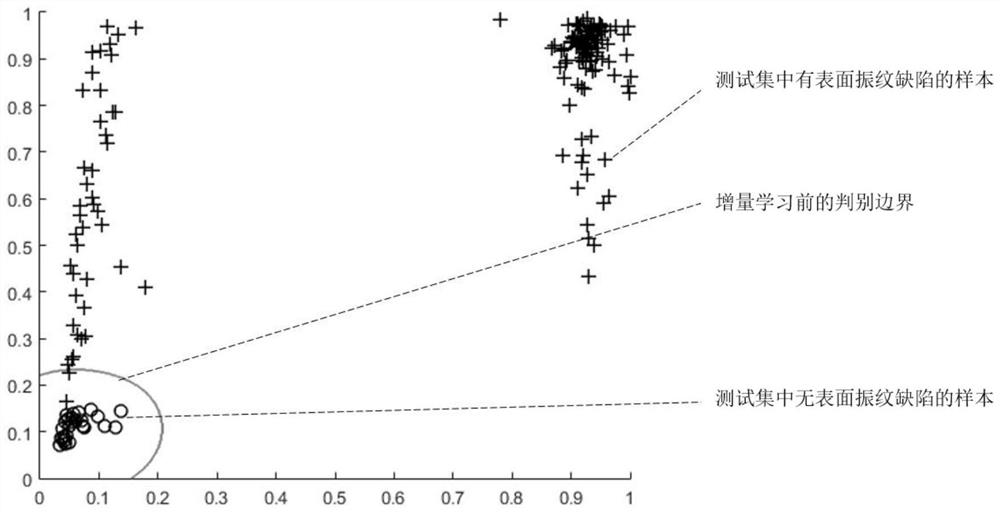
[0033] S2. Input the above vibration characteristics into the pre-trained chatter detection model, and judge the chatter state of the weakly rigid processing system currently used to process parts; if it is in the chatter state, there are chatter marks on the current processing surface of the part defect;

[0034] Wherein, the flutter detection model is a machine learning model; in ...

Embodiment 2

[0075]A computer-readable storage medium, the computer-readable storage medium includes a stored computer program, wherein when the computer program is run by a processor, the device where the storage medium is located is controlled to perform the processing provided in Embodiment 1 of the present invention Method for detection of vibration marks on the surface of parts. The relevant technical solutions are the same as those in Embodiment 1, and will not be repeated here.


PUM


Abstract

The invention discloses a machined part surface chatter mark defect detection method which comprises the following steps: measuring acceleration response signals of a cutter along the horizontal and vertical directions of a machine tool in the current machining process of a part, filtering cutter-pass harmonic components in the acceleration response signals, extracting wavelet entropy characteristics reflecting machining instability intensity in the acceleration response signals, and calculating the chatter mark defect of the machined part, recording the wavelet entropy characteristics as a vibration characteristic; inputting the vibration characteristics into a pre-trained flutter detection model, and judging the flutter state of a current weak-rigidity machining system for machining thepart; and if the part is in the flutter state, the current machining surface of the part has the chatter mark defect. After each part is machined, according to the accuracy of the current flutter detection model, on the basis of an existing flutter detection model, an incremental learning mode is adopted, continuously-accumulated actual measurement vibration information is utilized, some information which can have adverse effects on judgment precision is eliminated step by step, and therefore the accuracy of the flutter detection model is improved, and the accuracy of the flutter detection model is improved. And the detection precision of the machined surface chatter mark defects is high.

Description

technical field [0001] The invention belongs to the field of processing defect detection, and more specifically relates to a method for detecting vibration marks on the surface of a processed part. Background technique [0002] The surface vibration defects of parts determine the service performance and fatigue life of parts. Surface chatter marks are imprints engraved on the surface of the part by the vibration displacement of the cutter teeth during the machining process. Chatter marks are often caused by flutter in machining vibration, and the characteristics of chatter and chatter marks show a high similarity in frequency distribution. Therefore, the flutter information similar to the characteristics of the chattering defect can be extracted from the processing vibration signal as the basis for judging whether there is a chattering defect. [0003] During the machining process, the accurate judgment of machining chatter provides conditions for timely avoiding the deter...

Claims


Application Information

Patent Timeline
Patent Type & Authority Applications(China)
IPC IPC(8): G06F30/27G06K9/62G06F111/04G06F119/14
CPCG06F30/27G06F2111/04G06F2119/14G06F18/2411G06F18/214
Inventor 张小明曹乐丁汉夏峥嵘陶建民杨拥萍杨滨涛
Owner HUAZHONG UNIV OF SCI & TECH
Why Eureka
Try Eureka