
Automatic terminal riveting machine capable of carrying out sleeve processing on terminal

A technology of riveting presses and terminals, which is applied in the assembly/disassembly of contact parts, conductive connections, instruments, etc. It can solve the problems of high labor intensity, burns of employees' hands, and low efficiency, so as to improve production efficiency and avoid potential safety hazards , high safety effect

Active Publication Date: 2021-02-23
佛山市顺德区恒沃电器有限公司
View PDF18 Cites 4 Cited by
  • Summary
  • Abstract
  • Description
  • Claims
  • Application Information

AI Technical Summary

Problems solved by technology

[0003] In the prior art, the processing of the terminals is usually independent of each other, that is, after the terminals are wired and riveted, the terminals are manually removed and sleeved. Usually, the terminals are sleeved manually and hot air is held in hand. The gun heats the heat-shrinkable tube in all directions to make it heat-shrink, which is not only inefficient, but also labor-intensive. Improper use of the heat gun can easily cause burns to the hands of employees. The work is more dangerous and the product quality cannot be obtained. Guarantee, which increases the production cost of the enterprise and creates unnecessary burden

Method used


Image

  • Automatic terminal riveting machine capable of carrying out sleeve processing on terminal
  • Automatic terminal riveting machine capable of carrying out sleeve processing on terminal
  • Automatic terminal riveting machine capable of carrying out sleeve processing on terminal

Examples


Embodiment Construction

[0027] The following will clearly and completely describe the technical solutions in the embodiments of the present invention with reference to the accompanying drawings in the embodiments of the present invention. Obviously, the described embodiments are only some, not all, embodiments of the present invention.

[0028]In the description of the present invention, unless otherwise stated, the meaning of "plurality" is two or more; the terms "upper", "lower", "left", "right", "inner", "outer" , "front end", "rear end", "head", "tail", etc. indicate the orientation or positional relationship based on the orientation or positional relationship shown in the drawings, and are only for the convenience of describing the present invention and simplifying the description, rather than indicates or implies that the device or element referred to must have a particular orientation, be constructed and operate in a particular orientation, and therefore should not be construed as limiting the ...


PUM

PropertyMeasurementUnit
Thicknessaaaaaaaaaa

Abstract

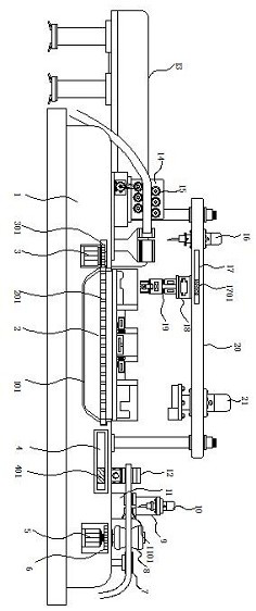
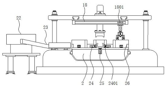
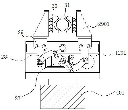
The invention discloses an automatic terminal riveting machine capable of carrying out sleeve processing on a terminal. The machine specifically comprises a base, a rotating disc, a functional clamp,a grabbing mechanism and a wiring terminal, a conveyor belt is mounted at one end of one side of the top of the base, and a heat shrink tube feeding mechanism is fixed at the other end of one side, close to the conveyor belt, of the top of the base; a rotating groove is formed in the middle of the top end of the interior of the base, the rotating disc is arranged in the rotating groove, limiting bases are evenly arranged at the edge of the top of the rotating disc, and hydraulic ejector rods are arranged in the portions, below the limiting bases, of the rotating disc. According to the automatic terminal riveting machine capable of carrying out sleeve processing on the terminal, by arranging the heat shrink tube feeding mechanism and the heat shrink tube limiting base, intelligent mechanical operation is achieved, manual tube penetrating or handheld hot air gun working is not needed, the machining efficiency is higher, the potential safety hazard that the hands of staff are scalded is avoided, and the use safety is higher.

Description

technical field [0001] The invention relates to the technical field of terminal riveting, in particular to an automatic terminal riveting machine capable of performing casing processing on terminals. Background technique [0002] The terminal block is an accessory product used to realize electrical connection. It is divided into the category of connectors in the industry. With the increasing degree of industrial automation and stricter and more precise industrial control requirements, the amount of terminal blocks is gradually increasing. With the development of the electronics industry, the use of terminal blocks is increasing, and there are more and more types. Before terminal wiring, it is usually necessary to peel the power wires, and then connect the stripped wires to the terminals and rivet them together. , In addition, in the production process, in order to prevent explosion and flame retardancy, it is usually necessary to perform casing treatment on the riveted termi...

Claims


Application Information

Patent Timeline
IPC IPC(8): H01R43/05H01R43/052H01R43/055H01R43/20H01R4/72G01N21/95G01B11/24
CPCH01R43/05H01R43/055H01R43/052H01R43/20H01R4/726G01N21/95G01B11/24
Inventor 张绍辉侯明彭达
Owner 佛山市顺德区恒沃电器有限公司
Learn More