Drilling device with dust removal function for stainless steel pipe production

A technology of stainless steel pipe and drilling device, which is applied in the direction of positioning device, driving device, boring/drilling, etc. It can solve the problems of poor dust removal effect, easy movement, and inability to ensure stability, so as to prevent movement, press and fix Guaranteed effect

Pending Publication Date: 2021-02-26
泰州市易达非机电制造有限公司
View PDF0 Cites 2 Cited by
  • Summary
  • Abstract
  • Description
  • Claims
  • Application Information

AI Technical Summary

Problems solved by technology

[0002] Stainless steel pipe is a hollow long round steel, widely used in petroleum, chemical, medical, food, light industry, mechanical instruments and other industrial pipelines and mechanical structural components, etc. In addition, when the bending and torsional strength are the same , light in weight, so it is also widely used in the manufacture of mechanical parts and engineering structures. When stainless steel pipes are connected to each other, it is usually necessary to drill holes in the pipe wall, and then use bolts to realize the installation and fixation between the pipes. The drilling device used in the production of stainless steel pipes in the prior art is relatively simple, and there are many deficiencies in the production of stainless steel pipes. The stability of the stainless steel pipe cannot be guaranteed when it is pressed and fastened. The effect of dust removal is poor, so the realization of a drilling device with dust removal function for stainless steel pipe production that can solve such problems is imperative

Method used


Image

  • Drilling device with dust removal function for stainless steel pipe production

Examples


Embodiment Construction

[0018]The technical solutions in the embodiments of the present invention will be clearly and completely described below in conjunction with the accompanying drawings in the embodiments of the present invention. Obviously, the described embodiments are only a part of the embodiments of the present invention, rather than all the embodiments. Based on the embodiments of the present invention, all other embodiments obtained by those of ordinary skill in the art without creative work shall fall within the protection scope of the present invention.

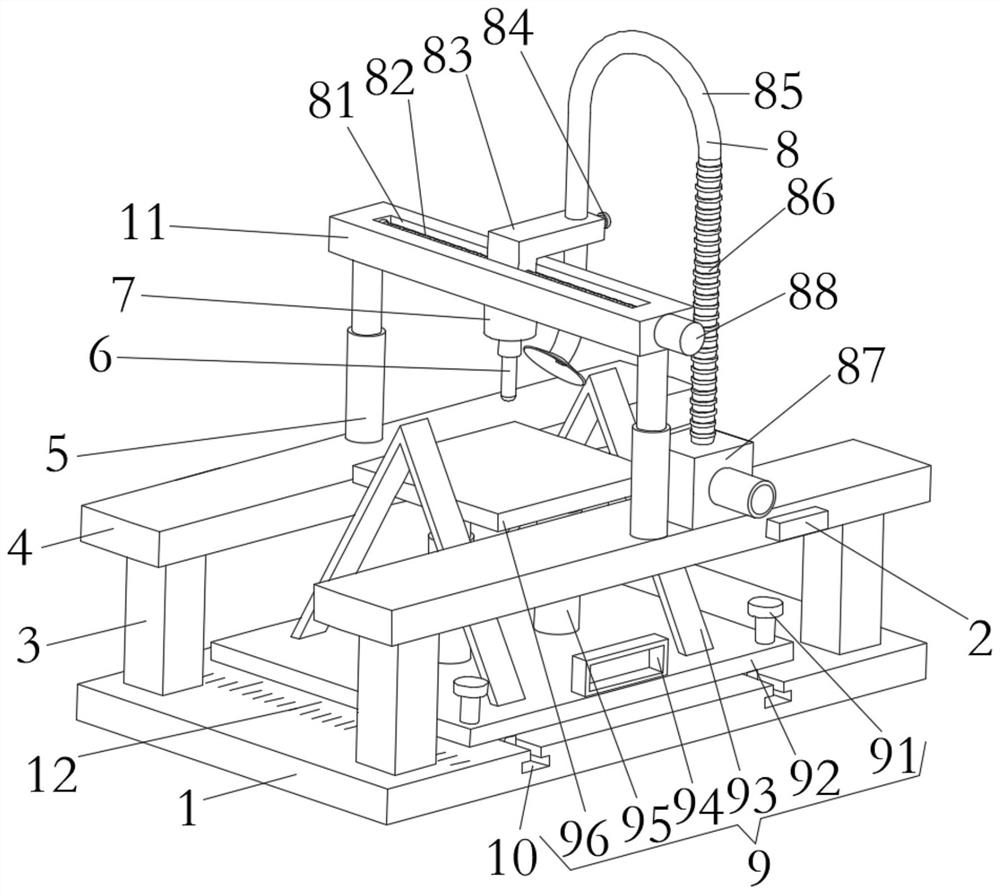
[0019]Seefigure 1, The present invention provides a technical solution: a drilling device with dust removal function for the production of stainless steel pipes, comprising a bottom plate 1, a dust removal structure 8 and a fixed adjustment structure 9;

[0020]Bottom plate 1: The upper surface of the bottom plate is symmetrically provided with a strip-shaped sliding opening 10, and the upper surface of the bottom plate 1 is provided with support ...


PUM


Abstract

The invention discloses a drilling device with a dust removal function for stainless steel pipe production. The drilling device comprises a bottom plate, a dust removal structure and a fixed adjustingstructure. Strip-shaped sliding openings are symmetrically formed in the middle of the upper surface of the bottom plate, supporting columns are symmetrically arranged at the four corners of the upper surface of the bottom plate, transverse plates are arranged at the upper ends of the two transversely-corresponding supporting columns correspondingly, first electric push rods are arranged in the middles of the upper surfaces of the transverse plates correspondingly, the upper ends of the telescopic ends of the first electric push rods are fixedly connected with the bottom face of a longitudinal plate, a first motor is arranged in the middle of the bottom surface of the longitudinal plate, and a drill bit is in threaded connection in a threaded hole in the lower end of an output shaft of the first motor. The dust removal structure is arranged on the upper surface of the longitudinal plate. The lower end of the fixed adjusting structure is in sliding connection with the two strip-shapedsliding openings. According to the drilling device with the dust removal function for stainless steel pipe production, pressing and fixing of stainless steel pipes with different diameters are achieved, the stability of the stainless steel pipes is guaranteed, and the dust removal effect is enhanced.

Description

Technical field[0001]The invention relates to the technical field of stainless steel pipe processing, in particular to a drilling device with dust removal function for the production of stainless steel pipes.Background technique[0002]Stainless steel pipe is a hollow long round steel, which is widely used in petroleum, chemical, medical, food, light industry, machinery and instrumentation and other industrial pipelines and mechanical structural parts. In addition, when the bending and torsion strength are the same , The weight is light, so it is also widely used in the manufacture of mechanical parts and engineering structures. When stainless steel pipes are connected and fixed to each other, it is usually necessary to drill the pipe wall, and then install and fix the pipe to the pipe through bolts. The drilling device for stainless steel pipe production in the prior art is relatively simple, and has many shortcomings for the production of stainless steel pipes. The stability of stai...

Claims


Application Information

Patent Timeline
Patent Type & Authority Applications(China)
IPC IPC(8): B23B41/00B23Q3/06B23Q5/04B23Q11/00
CPCB23B41/00B23Q3/06B23Q5/04B23Q11/0046
Inventor 刘志明李平
Owner 泰州市易达非机电制造有限公司
Why Eureka
Try Eureka