Marking machine for paper bag production
A technology of engraving machine and paper bag, which is applied in the direction of papermaking, bag making, paper/cardboard container, etc. It can solve the problems of troublesome operation and low work efficiency, and achieve the effect of preventing random movement
- Summary
- Abstract
- Description
- Claims
- Application Information
AI Technical Summary
Problems solved by technology
Method used
Image

Examples
Embodiment 1
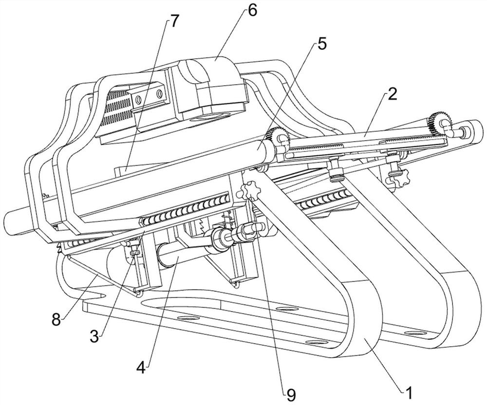
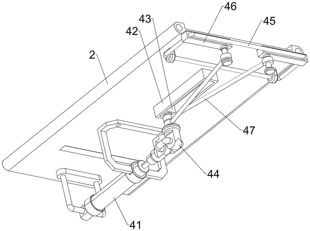
[0028] Such as Figure 1-Figure 5 As shown, a marking machine for paper bag production includes a frame 1, an inclined plate 2, a strip plate 3, a drive assembly 4, a clamping assembly 5, an engraving assembly 6 and a blocking assembly 7, and the upper part of the frame 1 is fixed by bolts. A slant plate 2 is connected, and the slant plate 2 is set to be high at the front and low at the rear. The left and right sides of the lower part of the slant plate 2 are fixed with long strip plates 3 by bolts. Both are provided with a clamping assembly 5 , an engraving assembly 6 is provided between the long strips 3 , and a blocking assembly 7 is provided at the back of the slant plate 2 .
[0029] When it is necessary to print text and patterns on the surface of the paper bag, first place the paper bag on the slant plate 2, the paper bag will slide down along the slant plate 2 to the bottom of the engraving assembly 6, and be blocked by the blocking assembly 7, so that the paper bag st...
Embodiment 2
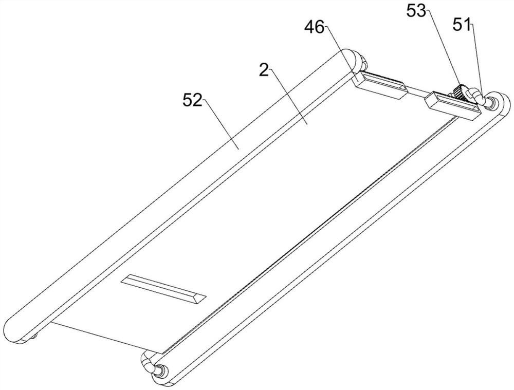
[0039] On the basis of Example 1, such as figure 1 , Figure 6 and Figure 7As shown, a pull assembly 8 is also included, and the pull assembly 8 includes a fan-shaped ratchet gear 81, a second slide block 83, a second spring 84, a ratchet bar 85, a guide plate 86 and a pull wire 87, and the special-shaped rod 51 on the rear side Both are connected with fan-shaped ratchet gears 81, and the left and right sides of the rear part of the swash plate 2 are provided with a second chute 82. The second chute 82 is slidably provided with a second slider 83, and the second slider 83 is connected to the swash plate 2. A second spring 84 is connected between them, a ratchet bar 85 is slidingly provided on the second slider 83, and the ratchet bar 85 is engaged with the fan-shaped ratchet gear 81, and the left and right sides of the rear portion of the swash plate 2 are connected with guide plates 86, The lower parts of the ratchet bars 85 on the left and right sides are all connected wi...
PUM
 Abstract
Description
Claims
Application Information