Hydraulic support pushing jack for half-well cutting coal-mining process
A technology of pushing jacks and hydraulic supports, applied in mine roof supports, mining equipment, earth-moving drilling, etc., can solve the problems of signal transmission delay, unstable pushing speed, and low precision of piston rod stroke control.
- Summary
- Abstract
- Description
- Claims
- Application Information
AI Technical Summary
Problems solved by technology
Method used
Image

Examples
Embodiment 1
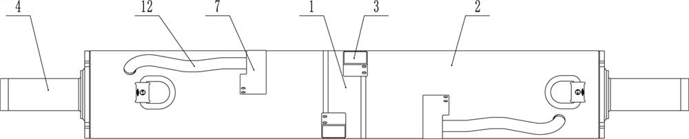
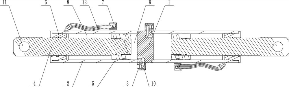
[0025] Such as figure 1 with figure 2 As shown, a hydraulic support push jack for the half-cut coal mining process includes a common cylinder bottom 1 and two sets of jack sets, the oil passages of the two sets of jack sets are independent of each other, and the two sets of jack sets use the shared cylinder bottom as The center extends to both ends and is arranged in a straight line, the far ends of the two sets of jack sets are connecting ears, the strokes of the two sets of jack sets are the same, and the left and right symmetrical arrangements of the two sets of jack sets are arranged.
[0026] The two sets of jack sets all include a cylinder 2, a bottom joint seat 3, a piston rod 4, a piston 5, a guide sleeve 6 and an intermediate joint seat 7, and the bottom ends of the cylinders 2 of the two sets of jack sets are respectively fixed on the common On the two end faces of the cylinder bottom 1, the guide sleeve 6 is mounted on the front end of the cylinder barrel 2, the p...
Embodiment 2
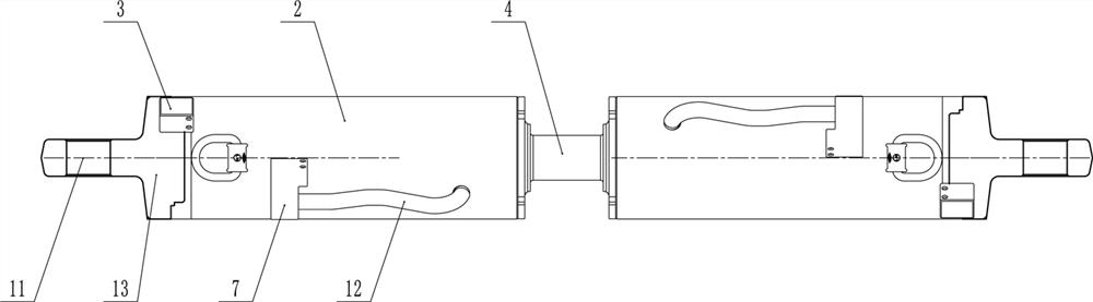
[0030] Such as image 3 with Figure 4 As shown, the difference between this embodiment and Embodiment 1 is that two sets of jack sets share a piston rod 4, the length of the piston rod is at least twice that of Embodiment 1, and the two sets of jack sets include cylinder barrel 2, bottom Joint seat 3, piston 5, guide sleeve 6 and intermediate joint seat 7, the cylinder barrels 2 of the two sets of jack kits are respectively set on the two ends of the piston rod 4 through the guide sleeve 6, and the two ends of the piston rod 4 are respectively installed with the piston 5 , the outer end of the cylinder 2 is blocked by the cylinder bottom 13, the connecting ear 11 is arranged at the outer end of the cylinder bottom 13, and the cylinder space is divided into the cylinder bottom cavity 9 and the cylinder cavity 8 by the piston 5 , the bottom joint seat 3 is embedded on the cylinder bottom 13 and communicates with the cylinder bottom cavity 9 through the liquid hole 10, and the ...
Embodiment 3
[0033] Such as Figure 5 with Image 6As shown, the difference between this embodiment and Embodiment 1 and Embodiment 2 lies in that: the cylinder bottom piston rod assembly 14 is designed integrally, one end is a cylinder bottom 15 structure, the other end is a piston rod 16 structure, and the jack kit located on the cylinder bottom side Including cylinder 2, piston rod 4, piston 5, guide sleeve 6, bottom joint seat 3 and intermediate joint seat 7, the bottom end of the cylinder barrel 2 is fixed on the cylinder bottom 15 side of the cylinder bottom piston rod assembly 14, The guide sleeve 6 is installed on the front end of the cylinder 2, the piston 5 is installed on the tail end of the piston rod 4, and the front end of the piston rod 4 extends outwards after passing through the guide sleeve 6, and one of the connecting ears 11 Located at the far end of the piston rod 4, the piston 5 divides the cylinder space into a cylinder bottom cavity 9 and a cylinder cavity 8, and t...
PUM
 Abstract
Description
Claims
Application Information
 - R&D
- Intellectual Property
- Life Sciences
- Materials
- Tech Scout
- Unparalleled Data Quality
- Higher Quality Content
- 60% Fewer Hallucinations
Browse by: Latest US Patents, China's latest patents, Technical Efficacy Thesaurus, Application Domain, Technology Topic, Popular Technical Reports.
© 2025 PatSnap. All rights reserved.Legal|Privacy policy|Modern Slavery Act Transparency Statement|Sitemap|About US| Contact US: help@patsnap.com