Rapid heat dissipation method for forklift control system

A technology of control system and heat dissipation method, which is applied in the direction of hoisting device, lifting equipment safety device, etc., can solve the problems of poor heat dissipation effect, achieve the effect of improving service life, simple and ingenious structure, and rapid cooling

Inactive Publication Date: 2021-02-26
张达宇
View PDF0 Cites 1 Cited by
  • Summary
  • Abstract
  • Description
  • Claims
  • Application Information

AI Technical Summary

Problems solved by technology

[0006] The purpose of the present invention is to address the deficiencies of the prior art, by setting the contact between the cooling medium and the hot gas, to achieve rapid cooling, and after cooling, use the cooling medium to discharge the cooling cycle, and at the same time realize the cooling after the cooling medium is discharged. On the other hand, every time the forklift is repaired, the side of the cooling medium ca

Method used


Image

  • Rapid heat dissipation method for forklift control system
  • Rapid heat dissipation method for forklift control system
  • Rapid heat dissipation method for forklift control system

Examples


Embodiment 1

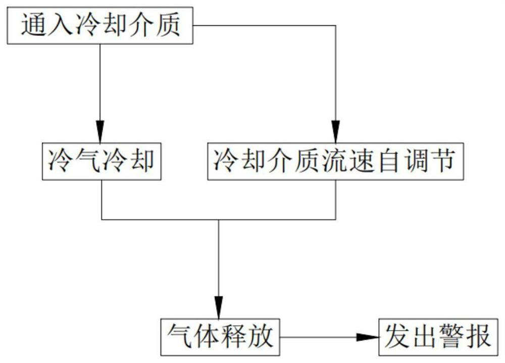
[0092] Such as figure 1 As shown, a method for rapid cooling of a forklift control system, including:

[0093] Step 1, feed cooling medium, when the car body 101 starts, the drive shaft 105 drives the wheel 104 to rotate, the rotating drive shaft 105 drives the connecting shaft 42 of the driving assembly 4 to rotate, the rotating connecting shaft 42 drives the driving gear a43 to rotate, and the rotating When the driving gear a43 meshes with the driving rack a44, the driving rack a44 is lifted up to open the touch switch on the turbine water pump, and the turbine water pump drives the water circulation transmission;

[0094] Step 2, the hot air is cooled, the cooling water rushes into the elastic water pipe 221 of the cooling assembly 22, and the elastic water pipe 221 expands. The distance between them is zero, and the hot air is blocked by the elastic water pipe 221, and the cooling work is completed during the blocking process;

[0095] Step 3, self-regulation of the flow...

Embodiment 2

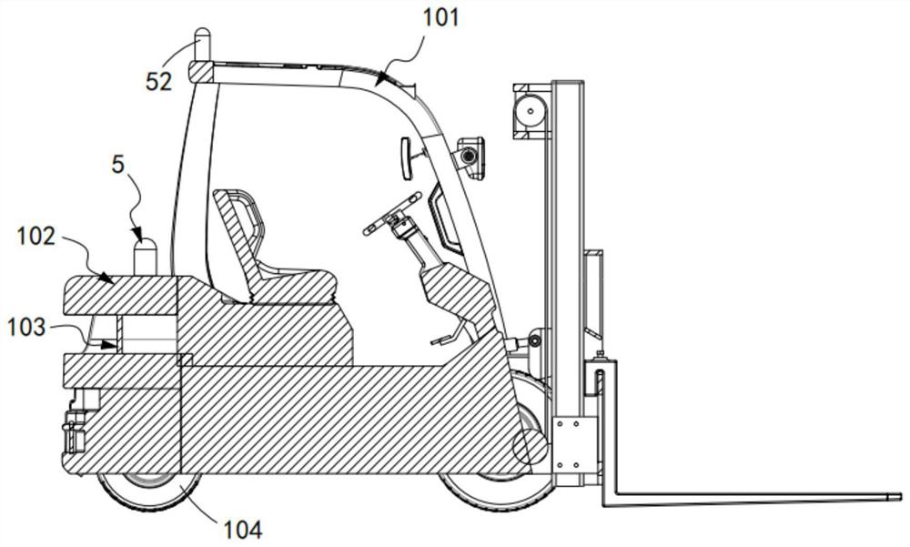
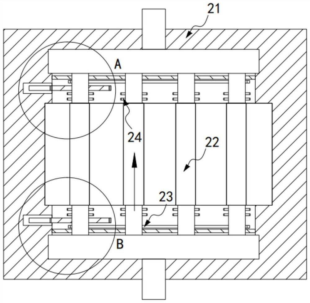
[0109] Such as image 3 , figure 2 As shown, a heat dissipation device for a control system of an electric counterweight forklift includes a vehicle body 101, a counterweight body 102 installed on the vehicle body 101, and a cooling port 103 provided on the counterweight body 102, and also includes:

[0110] The heat dissipation assembly 2, the heat dissipation assembly 2 includes a support assembly 21 installed on the counterweight body 102 and located outside the heat dissipation port 103, a cooling assembly 22 arranged on the support assembly 21, and used to drive the A switching assembly 23 for switching the cooling assembly 22 and a torsion assembly 24 for tightening the cooling assembly 22;

[0111] A circulation assembly 3, the circulation assembly 3 is arranged on the support assembly 21 and communicated with the heat dissipation assembly 2;

[0112] Drive assembly 4, described drive assembly 4 drives described circulation assembly 3 to carry out circular transmissi...

Embodiment 3

[0164] Such as Figure 11 to Figure 13 As shown, the parts that are the same as or corresponding to those in the second embodiment are marked with the corresponding reference numerals in the second embodiment. For the sake of simplicity, only the differences from the second embodiment will be described below. The difference between this embodiment three and embodiment two is:

[0165] further, such as Figure 11 to Figure 13 As shown, the torsion assembly 24 includes:

[0166] The active part 241, the active part 241 includes a floating ball 2411 located in the second water pipe 38, two sets of limit blocks 2412 respectively located on the upper and lower sides of the floating ball 2411 and the floating ball 2411 The lower end is fixedly connected and slides vertically through the top supporting shaft 2413 provided on the upper end of the cooling box 36, and the limiting block 2412 is fixedly arranged in the second water pipe 38;

[0167] The transmission member 242, the tr...


PUM


Abstract

The invention relates to a rapid heat dissipation method for a forklift control system. The rapid heat dissipation method comprises the steps that 1, a cooling medium is introduced; 2, hot air coolingis conducted; 3, the flow speed of the cooling medium is adjusted automatically and is synchronous with the second step; 4, air is released; and 5, an alarm is given. The rapid heat dissipation method solves the technical problems that in the driving process of a forklift, heat emitted by a heat dissipation element is not used due to different forklift speeds, and consequently the heat dissipation effect is poor through the same heat dissipation manner and degree.

Description

technical field [0001] The invention relates to the technical field of forklifts, in particular to a rapid heat dissipation method for a control system of a forklift. Background technique [0002] The temperature control of the electric counterbalanced forklift controller plays a vital role in the performance of the forklift. If the controller cannot dissipate heat sufficiently, it will seriously affect the performance of the forklift. When the temperature of the controller exceeds a certain set temperature, the maximum current will decrease proportionally with the increase of temperature. When overheating, the controller reduces the output torque by cutting the current. [0003] When the electric counterbalanced forklift works without stopping for a long time, especially when it is fully loaded and climbing, the temperature of the controller will rise rapidly. When the convection cooling type or contact cooling cannot dissipate the generated heat, the controller will work...

Claims


Application Information

Patent Timeline
IPC IPC(8): B66F9/075B66F17/00
CPCB66F9/07595B66F17/003
Inventor 张达宇
Owner 张达宇
Why Eureka
Try Eureka