Optical fiber preform manufacturing equipment

A technology for optical fiber preform and manufacturing equipment, which is applied in glass manufacturing equipment, manufacturing tools, etc. It can solve problems such as inconsistent reaction concentration and axial unevenness of optical rods, and achieve the effect of ensuring consistency and improving axial uniformity

Active Publication Date: 2021-02-26
FENGHUO COMM SCI & TECH CO LTD +1
View PDF9 Cites 2 Cited by
  • Summary
  • Abstract
  • Description
  • Claims
  • Application Information

AI Technical Summary

Problems solved by technology

[0005] Aiming at the defects existing in the prior art, the object of the present invention is to provide a kind of optical fiber preform manufacturing equipment, which can solve the inconsistency of the reaction concentration of the reactants in the reaction tube at each deposition point in the prior art, which will cause the optical rod to be in the axial direction. uneven upwards problem

Method used


Image

  • Optical fiber preform manufacturing equipment
  • Optical fiber preform manufacturing equipment
  • Optical fiber preform manufacturing equipment

Examples


Embodiment Construction

[0028] In order to make the purposes, technical solutions and advantages of the embodiments of the present application clearer, the technical solutions in the embodiments of the present application will be clearly and completely described below in conjunction with the drawings in the embodiments of the present application. Obviously, the described embodiments It is a part of the embodiments of this application, but not all of them. Based on the embodiments in the present application, all other embodiments obtained by persons of ordinary skill in the art without making creative efforts belong to the protection scope of the present application.

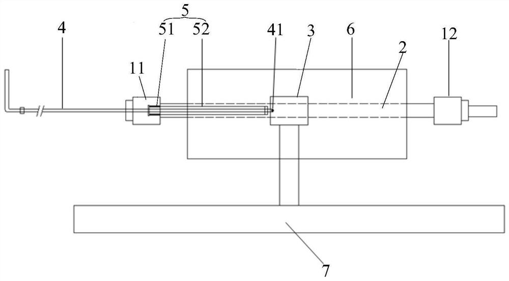
[0029] Embodiments of the present invention will be described in further detail below in conjunction with the accompanying drawings. figure 1 It is a schematic structural diagram of the optical fiber preform manufacturing equipment in the embodiment of the present invention, such as figure 1 Shown:

[0030] The present invention provi...


PUM


Abstract

The invention relates to the technical field of optical fiber preform production, in particular to optical fiber preform manufacturing equipment which comprises a sealing mechanism, a microwave resonant cavity and an air inlet pipe, wherein the sealing mechanism comprises an air inlet end sealing piece and an air outlet end sealing piece arranged at an interval for sealing the two ends of a reaction pipe; the microwave resonant cavity is used for being arranged on the outer side of the reaction tube in a sleeving manner and can do reciprocating motion in the axial direction of the reaction pipe; and the air inlet pipe comprises an air outlet end used for extending into the reaction pipe, the air inlet pipe penetrates through the air inlet end sealing piece, and the air outlet end is configured to synchronously reciprocate with the resonant cavity in the reaction pipe. The problem that in the prior art, due to the fact that the reaction concentrations of reactants in a reaction pipe atall deposition points are inconsistent, an optical wand is not uniform in the axial direction can be solved.

Description

technical field [0001] The invention relates to the technical field of optical fiber preform production, in particular to an optical fiber preform production equipment. Background technique [0002] In recent years, with the large-scale deployment of 4G and the commercial use of 5G, the digitalization process is advancing rapidly, and people's demand for data transmission is also increasing day by day. At the same time, as the most important part of data transmission, communication optical fiber has always been concerned by people. [0003] The PCVD plasma chemical vapor deposition process is currently the most commonly used method for preparing communication optical fibers. This process can deposit thousands of layers, so it is very precise in waveguide structure design, material composition and structure design. It has the characteristics of high-precision refractive index distribution control, high deposition efficiency, and excellent flexibility. The PCVD process can n...

Claims


Application Information

Patent Timeline
IPC IPC(8): C03B37/018
CPCC03B37/01815
Inventor 刘旋郭浩喻煌岳静谢校臻
Owner FENGHUO COMM SCI & TECH CO LTD
Why Eureka
Try Eureka