Settled ash conveying system and method
A technology of conveying system and settling ash, which is applied in the direction of combustion method, lighting and heating equipment, and treatment of combustion products. It can solve problems such as ash blocking, increased maintenance, and increased power consumption, so as to achieve enhanced fluidity and reliable operation. , The effect of convenient maintenance
- Summary
- Abstract
- Description
- Claims
- Application Information
AI Technical Summary
Problems solved by technology
Method used
Image

Examples
Embodiment Construction
[0020] The present invention will be further described below in conjunction with the accompanying drawings.
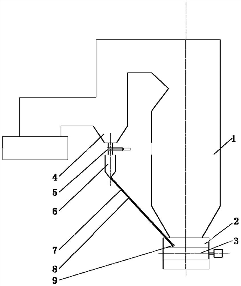
[0021] see figure 1 , a settling ash conveying system, including a boiler 1, a settling ash hopper 4 is arranged at the turning point of the boiler 1, a dry slag machine 2 is arranged under the boiler 1, the lower part of the settling ash hopper 4 is connected with a settling ash bin 6, and the settling ash bin 6 The sedimentation ash conveying pipeline 7 is connected with the slag drying machine 2 , the slag drying machine conveying steel belt 3 is arranged under the slag drying machine 2 , and an ash outlet is opened on the slag drying machine 2 . An inlet shut-off door 5 is arranged on the connecting pipeline between the settling ash hopper 4 and the settling ash bin 6 . An air locker 8 is arranged on the settled ash conveying pipeline 7 . One end of the settled ash conveying pipeline 7 is located in the slag dryer 2 . The ash outlet adopts bell mouth 9.
[0022...
PUM
 Abstract
Description
Claims
Application Information
 - R&D
- Intellectual Property
- Life Sciences
- Materials
- Tech Scout
- Unparalleled Data Quality
- Higher Quality Content
- 60% Fewer Hallucinations
Browse by: Latest US Patents, China's latest patents, Technical Efficacy Thesaurus, Application Domain, Technology Topic, Popular Technical Reports.
© 2025 PatSnap. All rights reserved.Legal|Privacy policy|Modern Slavery Act Transparency Statement|Sitemap|About US| Contact US: help@patsnap.com