Automatic transmission and installation system for cabin vibration testing

A vibration testing and automatic transmission technology, applied in vibration testing, measuring devices, transportation and packaging, etc., can solve the problems of high labor intensity, low automation level, low work efficiency, etc., to improve traceability and production efficiency. , the effect of reducing labor intensity

Active Publication Date: 2021-02-26
CHINA ELECTRONICS TECH GRP CORP NO 14 RES INST
View PDF11 Cites 1 Cited by
  • Summary
  • Abstract
  • Description
  • Claims
  • Application Information

AI Technical Summary

Problems solved by technology

[0003] Regarding the vibration test operation of the control cabin and the instrument cabin, the existing operation mode is that the operator will carry the test piece from the outside of the test room to the test vibration table, and manually Operating skills for positioning, fastening and clamping, low automation level
[0004] During the operation process of the control cabin and the instrument cabin vibration electrification test, on the one hand, the two cabin sections are clamped on the same vibration tool by the test piece, and the overall weight is heavy, so it is difficult to carry The labor intensity is high; on the other hand, operators need to repeatedly enter the test room to perform manual clamping operations. There are certain risks to the reliability of clamping and the safety of operators, and the work efficiency is low.

Method used


Image

  • Automatic transmission and installation system for cabin vibration testing
  • Automatic transmission and installation system for cabin vibration testing
  • Automatic transmission and installation system for cabin vibration testing

Examples


Embodiment 1

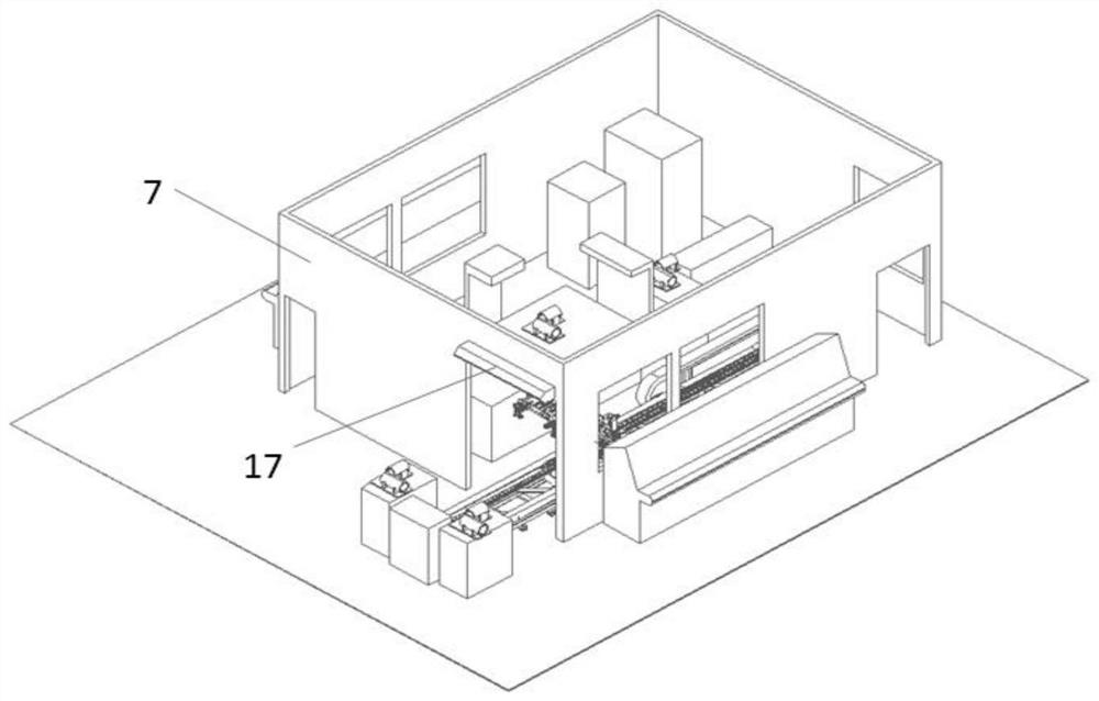
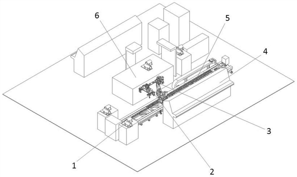
[0029] see Figure 1~5, in an embodiment of the present invention, an automatic transmission and installation system for cabin vibration testing, including an L-shaped fixed cabin fixture 1, a clamping and grabbing tool 2, a robot 3, a robot control system 4, a robot guide rail 5, a vibration table 6 and The vibration test isolation room 7, wherein the vibration table 6 is fixedly installed in the middle position inside the vibration test isolation room 7, and the side wall of the vibration table 6 is provided with a robot guide rail 5, and the robot guide rail 5 is fixedly installed in the vibration test isolation room 7 and one end of the robot guide rail 5 protrudes from the vibration test isolation room 7. At the same time, a robot 3 is installed on the robot guide rail 5. The position of the manipulator of the robot 3 is fixedly equipped with a clamping and grabbing tool 2, and the vibration test isolation room 7 The robot control system 4 is fixedly installed on the side...

Embodiment 2

[0036] see Figure 1-7 , the main structure of this embodiment is the same as that of Embodiment 1, the difference is that: Considering that the experimental cabin section may move on the cabin section fixing fixture 15 during the vibration test process, for this reason, in the cabin section fixing fixture 15 The top is provided with a cover plate 18, the shape of the cover plate 18 is the same as the shape of the cabin fixing fixture 15, and a pair of lower side ears 19 are fixedly installed on the left and right side walls of the top of the cabin fixing fixture 15, and the cover plate 18 A pair of upper ears 20 are fixedly installed on the two side walls of the bottom, wherein the lower ears 19 and the upper ears 20 are fixedly installed together by fixing bolts 21, and the test cabin is fixedly installed between the cabin fixing fixture 15 and the cover plate 18.

[0037] Wherein, the top of the cover plate 18 is provided with a threaded hole 22, the threaded hole 22 is int...


PUM


Abstract

The invention, which relates to the technical field of the lifesaving apparatus, discloses an automatic transmission and installation system for cabin vibration testing. The system comprises an L-shaped fixed cabin clamp, a clamping and grabbing tool, a robot, a robot control system, a robot guide rail, a vibration table and a vibration test isolation room. The robot is installed on the guide rail, the robot integrates an intelligent visual system with photographing and motion control functions and a grabbing and fastening tool. A conveying guide rail is of a structure with a rack and has a motor-driven gear and rack pair transmission function. The L-shaped fixed cabin clamp realizes the flexibility of a vibration test unit by replacing the cabin fixed clamp; the robot control system is aservo control and safety linkage protection system for robot movement. The automatic transmission and installation system is a cabin vibration test automatic transmission and installation intelligentunit system integrating flexibility, automation and informatization, meets the operation improvement requirement that manual operation is not needed in the operation process, improves the safety, andimproves the production efficiency.

Description

technical field [0001] The invention relates to the technical field of intelligent manufacturing automatic transmission and assembly, in particular to an automatic transmission and installation system for cabin vibration testing. Background technique [0002] After the integrated assembly of the control cabin and the instrument cabin of a product is completed, a vibration power-on test is required. The vibration electrification test is carried out in a dedicated isolated test room. The main equipment in the test room is a vibration table, electrification equipment, control cabinet, test tooling and other equipment. Before the test, the test piece needs to be transported from the outside of the test room to the test vibration table for clamping, and after the vibration test in one direction is completed, the clamping in the other direction is switched to the vibration test. The total test time for the two directions is 45 minutes . The clamping of the test piece on the vibr...

Claims


Application Information

Patent Timeline
Patent Type & Authority Applications(China)
IPC IPC(8): G01M7/02G01R31/00B65G47/90
CPCG01M7/02G01M7/027G01R31/003B65G47/905
Inventor 严战非徐彪从梦磊杨帆
Owner CHINA ELECTRONICS TECH GRP CORP NO 14 RES INST
Why Eureka
Try Eureka