
Positioning device based on 3D laser radar measurement

A technology of laser radar and positioning device, which is applied in the direction of measuring device, radio wave measuring system, electromagnetic wave reradiation, etc., can solve the problems of limited measurement angle of view, bulky device, and insufficient measurement accuracy, so as to improve support adaptability and support Effect, measurement of accurate and efficient effect

Pending Publication Date: 2021-02-26
龚文凯
View PDF0 Cites 2 Cited by
  • Summary
  • Abstract
  • Description
  • Claims
  • Application Information

AI Technical Summary

Problems solved by technology

[0003] Existing laser radar is mostly used for 3D measurement and positioning equipment, relying on laser radar for measurement, after measurement, objects are identified and modeled to realize three-dimensional measurement and positioning, but when the existing measurement and positioning devices are used, often the laser radar cannot be rotated Or moving, the measurement angle of view is very limited, and it is easily affected by the cover, resulting in insufficient measurement accuracy. The existing measurement positioning device has poor support when used, and it is easy to cause damage to the laser radar in harsh environments, and the existing measurement positioning device The device is less convenient to use and the device is cumbersome

Method used

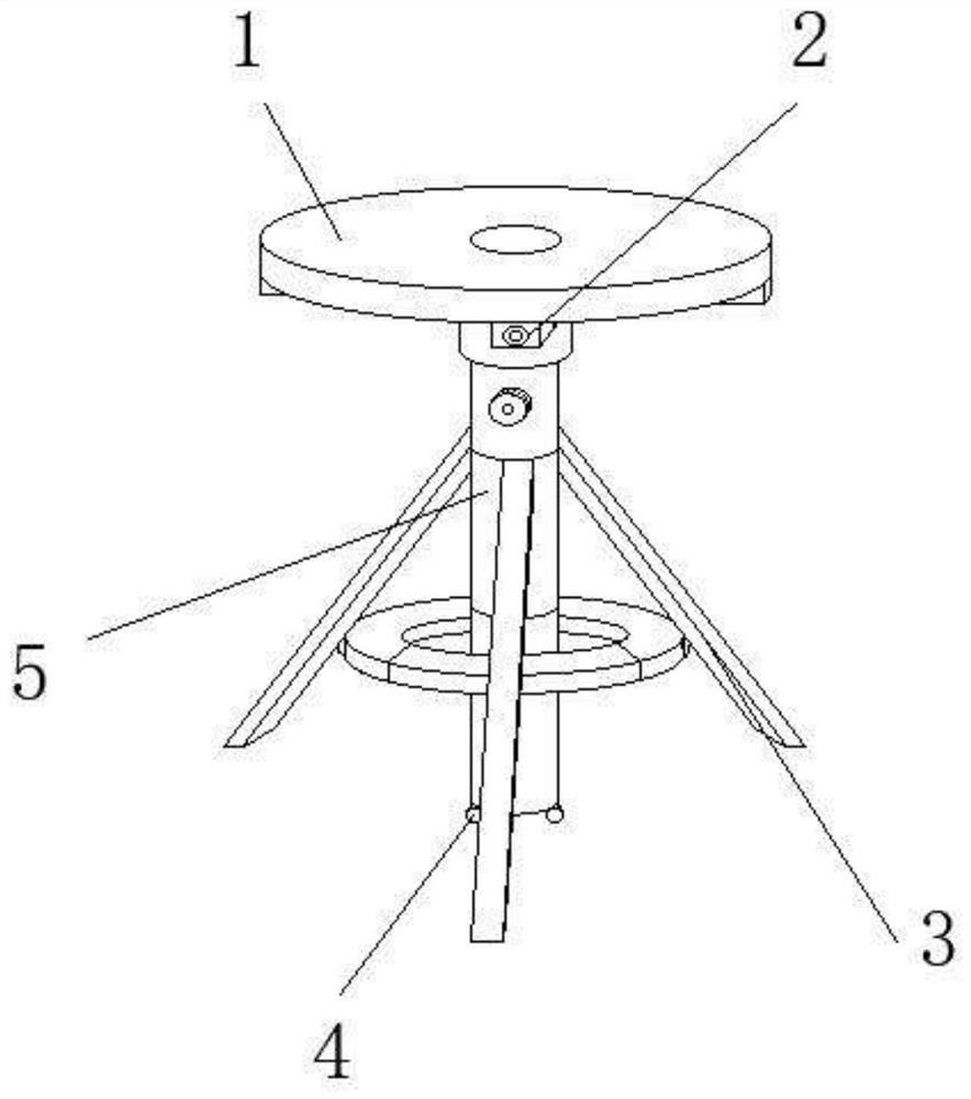

Image

  • Positioning device based on 3D laser radar measurement
  • Positioning device based on 3D laser radar measurement
  • Positioning device based on 3D laser radar measurement

Examples


Embodiment Construction

[0029] Embodiments of the present invention are described in detail below, examples of which are shown in the drawings, wherein the same or similar reference numerals denote the same or similar elements or elements having the same or similar functions throughout. The embodiments described below by referring to the figures are exemplary only for explaining the present invention and should not be construed as limiting the present invention.

[0030] In describing the present invention, it is to be understood that the terms "center", "longitudinal", "transverse", "length", "width", "thickness", "upper", "lower", "front", " Orientation indicated by rear, left, right, vertical, horizontal, top, bottom, inside, outside, clockwise, counterclockwise, etc. The positional relationship is based on the orientation or positional relationship shown in the drawings, which are only for the convenience of describing the present invention and simplifying the description, rather than indicating ...


PUM


Abstract

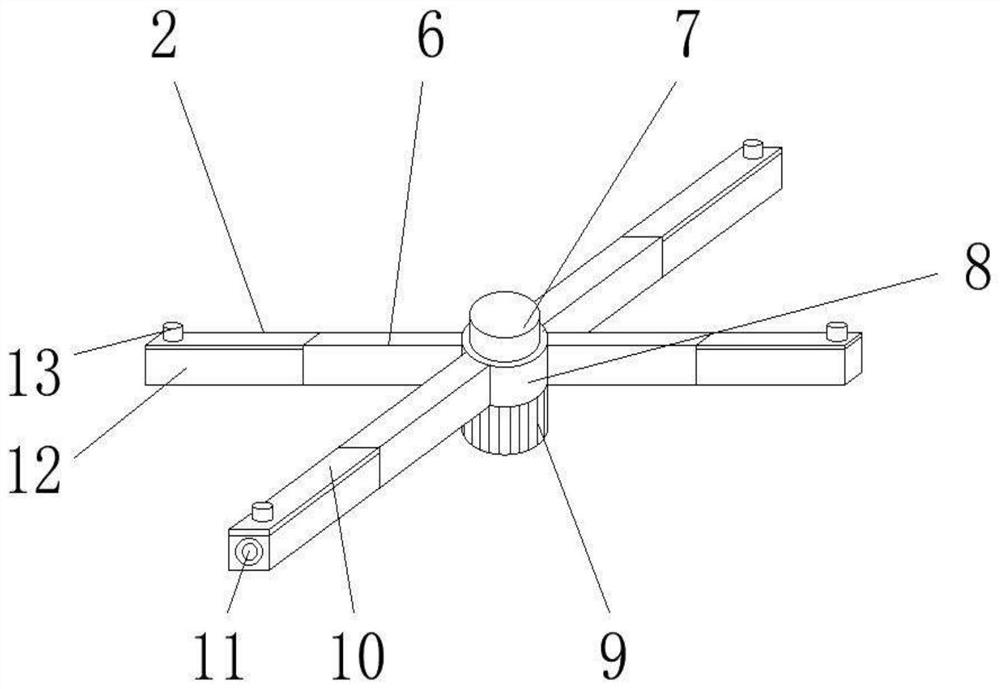
A 3D laser radar measurement-based positioning device provided by the present invention comprises a rotation measurement device, the rotation measurement device comprises a connection rod, a first rotation shaft, a support main body, a driving motor, a connection plate, a laser measurement radar, a telescopic rod and a first sliding block, and the driving motor is rotatably connected to the lowerend surface of the support main body. The first rotating shaft is rotationally connected to the upper end face of the support body, the connecting rod is fixedly connected to the periphery of the sideend face of the support body, the connecting plate is fixedly connected to the side, deviating from the support body, of the connecting rod, and the telescopic rod is slidably connected into the connecting rod in a sleeved mode. The laser measuring radar is fixedly connected to the end, deviating from the connecting rod, of the telescopic rod, the first sliding block is fixedly connected to the upper end face of the connecting plate, the upper end face of the rotary measuring device is rotationally connected with a protective baffle, the stability of the measuring and positioning device during measurement is effectively improved, and the measuring precision is improved through multi-angle measurement.

Description

technical field [0001] The invention relates to the field of positioning equipment, in particular to a positioning device based on 3D laser radar measurement. Background technique [0002] Lidar refers to an active remote sensing device that uses a laser as a source of emission and uses photoelectric detection technology. Lidar is an advanced detection method combining laser technology and modern photoelectric detection technology. It is composed of transmitting system, receiving system, information processing and other parts. The transmitting system is composed of various forms of lasers, such as carbon dioxide lasers, neodymium-doped yttrium aluminum garnet lasers, semiconductor lasers, wavelength-tunable solid-state lasers, and optical beam expanders; the receiving system uses telescopes and various forms of photodetectors , such as photomultiplier tubes, semiconductor photodiodes, avalanche photodiodes, infrared and visible light multiplex detection devices, and other ...

Claims


Application Information

Patent Timeline
Patent Type & Authority Applications(China)
IPC IPC(8): G01S17/06G01S7/481F16M11/08F16M11/04F16M11/18F16M11/24
CPCG01S17/06G01S7/4811G01S7/4817F16M11/08F16M11/048F16M11/18F16M11/242F16M11/245F16M11/247F16M2200/066
Inventor 龚文凯邹捷黄桂林胡戈飙杨玎任振远林志驰张霄许瑞庆陈大光
Owner 龚文凯
Learn More