
Chip packaging structure easy to dissipate heat, and packaging method thereof

A technology of chip packaging structure and heat dissipation device, which is applied in the direction of electrical components, electric solid devices, circuits, etc., can solve the problems of unreasonable chip packaging structure design, sealing can not take into account heat dissipation, shortened service life, etc., and achieves the convenience of pin adjustment angle , Easy overall installation and prolong service life

Inactive Publication Date: 2021-02-26
王海魁
View PDF0 Cites 7 Cited by
  • Summary
  • Abstract
  • Description
  • Claims
  • Application Information

AI Technical Summary

Problems solved by technology

[0003] When the chip is working, a large amount of heat energy is often generated. If the heat energy cannot be dissipated in time and continues to accumulate in the chip, the temperature of the chip will continue to rise. Over time, the performance of the chip is likely to decline due to overheating. Or the service life is shortened, and serious cases even cause permanent damage. The existing chip packaging structure design is unreasonable, and heat dissipation cannot be taken into account while achieving sealing. The heat dissipation effect is poor and the service life is short. Therefore, those skilled in the art provide a A chip packaging structure and packaging method thereof that are easy to dissipate heat, so as to solve the problems raised in the above-mentioned background technology

Method used


Image

  • Chip packaging structure easy to dissipate heat, and packaging method thereof
  • Chip packaging structure easy to dissipate heat, and packaging method thereof
  • Chip packaging structure easy to dissipate heat, and packaging method thereof

Examples


Embodiment Construction

[0036] The following will clearly and completely describe the technical solutions in the embodiments of the present invention in conjunction with the accompanying drawings in the embodiments of the present invention; obviously, the described embodiments are only part of the embodiments of the present invention, not all embodiments, based on The embodiments of the present invention and all other embodiments obtained by persons of ordinary skill in the art without making creative efforts belong to the protection scope of the present invention.

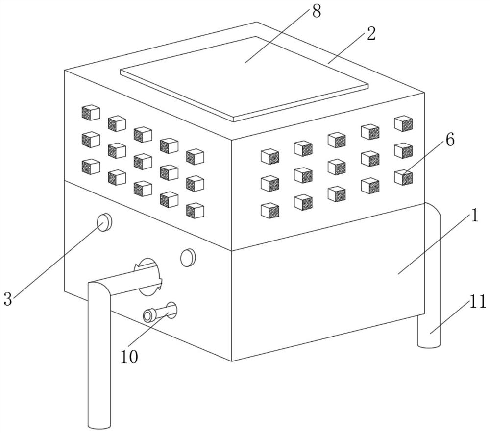
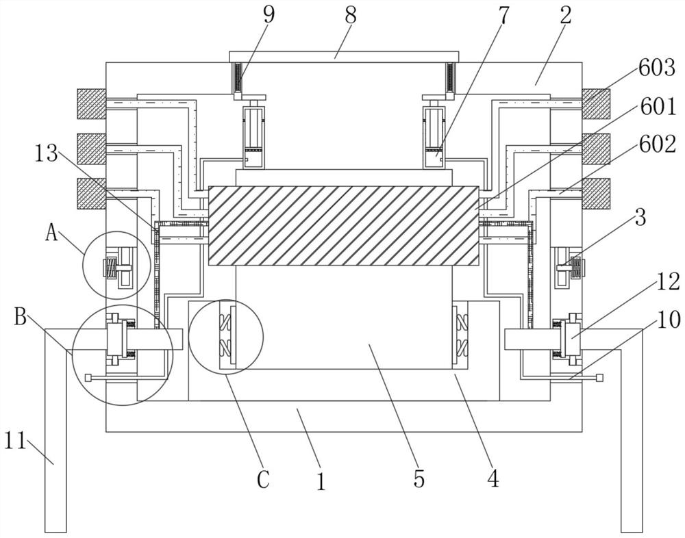
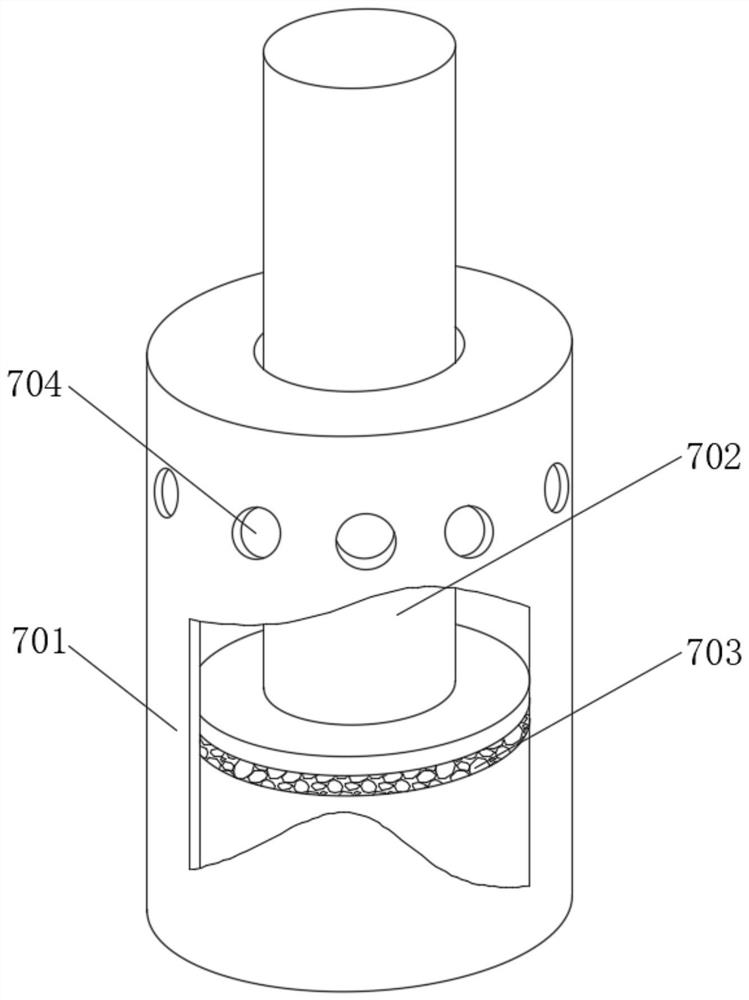
[0037] see Figure 1-7, in an embodiment of the present invention, a chip packaging structure that is easy to dissipate heat includes a lower box body 1, an upper box body 2 is clamped on the top of the lower box body 1, and two sides of the lower box body 1 are provided with two The clamping device 3, the clamping device 3 penetrates the lower box body 1 and is clamped with the upper box body 2, the inner bottom wall of the lower box bo...


PUM


Abstract

The invention discloses an easy-to-radiate chip packaging structure and a packaging method thereof, and belongs to the technical field of electronic components. The easy-to-radiate chip packaging structure is characterized by comprising a lower box body, wherein an upper box body is clamped to the top of the lower box body, two clamping devices are arranged on each of the two sides of the lower box body, the clamping device penetrates through the lower box body and is connected with the upper box body in a clamped mode, a mounting assembly is fixedly connected to the inner bottom wall of the lower box body, and a chip body is arranged on the inner bottom wall of the mounting assembly. According to the invention, by arranging a pushing device, when a chip body works, a cover plate can be driven to ascend to generate deformation, so that conversion can be carried out according to the working condition of the chip body, sealing and dust prevention are achieved when the chip body does notwork, dust is prevented from entering the chip body, heat dissipation is carried out in time when the chip body works, the heat dissipation effect is good, and the service life of the device is prolonged; and through holes in the surface of the pushing device can drive the cover plate to move up and down, so that and flowing of air between the upper box body and the lower box body can be accelerated, and heat dissipation effect is better.

Description

technical field [0001] The invention relates to the technical field of electronic components, and more specifically, relates to a chip package structure and a package method thereof which are easy to dissipate heat. Background technique [0002] Chips, also known as microcircuits, microchips, and integrated circuits, refer to silicon chips containing integrated circuits. They are small in size and are often part of computers or other electronic equipment. The results of design, manufacture, packaging, and testing, and integrated circuits are the most important part of electronic equipment, which undertakes the functions of computing and storage. The application range of integrated circuits covers almost all electronic equipment for military and civilian use. Packaging is The process of assembling an integrated circuit into a chip final product, simply put, is to put the bare integrated circuit chip produced by the manufacturer on a substrate that acts as a load bearing, lead...

Claims


Application Information

Patent Timeline
Patent Type & Authority Applications(China)
IPC IPC(8): H01L23/04H01L23/10H01L23/36H01L23/32H01L23/488
CPCH01L23/04H01L23/10H01L23/32H01L23/36H01L23/488
Inventor 王海魁
Owner 王海魁
Learn More