Wireless charging system and constant-current/constant-voltage charging optimization control method

A technology of wireless charging and charging current, applied in the direction of secondary battery charging/discharging, battery circuit device, secondary battery repair/maintenance, etc. Sampling difficulty, etc.

Active Publication Date: 2021-02-26
JIANGNAN UNIV
View PDF1 Cites 1 Cited by
  • Summary
  • Abstract
  • Description
  • Claims
  • Application Information

AI Technical Summary

Problems solved by technology

[0005]In order to solve the unstable operation of the system caused by the charging control of the existing wireless charging system by means of wireless communication, the difficulty of sampling high-frequency current and voltage inside the system, and the need to meet constant It is difficult to optimize the power transmission efficiency of the system while meeting the requirements of current / constant voltage charging. The present invention provides a control method based on wireless charging system and constant current / constant voltage charging optimization to realize the control of voltage / current in wireless charging technology. Accurate control and optimization of system power transfer efficiency

Method used


Image

  • Wireless charging system and constant-current/constant-voltage charging optimization control method
  • Wireless charging system and constant-current/constant-voltage charging optimization control method
  • Wireless charging system and constant-current/constant-voltage charging optimization control method

Examples


Embodiment 1

[0066] This embodiment provides a wireless charging system, the primary side and the secondary side of the system are independently controlled, and the primary side of the system includes: an input power supply, a Buck circuit, a full-bridge inverter, and a primary side transmitting and receiving and compensation circuit and the MCU on the primary side; the secondary side of the system includes: a load, a Boost circuit, a full-wave rectifier, a secondary side transmitting and receiving and compensation circuit, and a secondary side MCU;

[0067] The primary side of the system is also provided with a current / voltage sampling circuit; the MCU of the primary side is connected with the output port of the primary side sampling circuit to obtain the DC current value I outputted by the primary side Buck circuit. out and DC voltage value U out ;

[0068] The MCU on the primary side is connected to the control input port of the Buck circuit on the primary side; the MCU on the primary ...

Embodiment 2

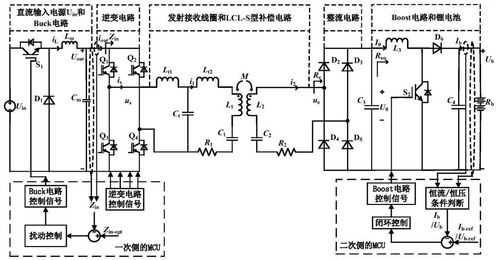
[0073]This embodiment provides a wireless charging system, the primary side and the secondary side of the system are independently controlled, see figure 1 , the wireless charging system includes: DC input voltage source U in , Buck circuit, inverter circuit, transmitting and receiving coil, LCL-S type compensation circuit, rectifier circuit, Boost circuit and lithium battery.

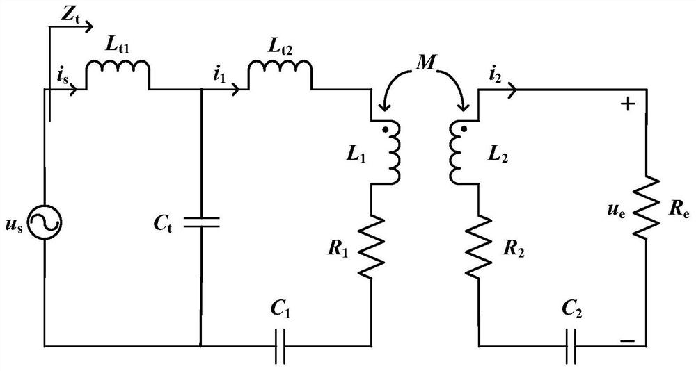
[0074] In this embodiment, the transmitting coil and compensation circuit on the primary side and the receiving coil and compensation circuit on the secondary side are the transmitting and receiving coil and the LCL-S type compensation circuit in the figure, and the load is illustrated by taking a lithium battery as an example.

[0075] like figure 1 As shown, one DC input terminal of the Buck circuit is connected to the DC input voltage source U in The positive pole of the Buck circuit is connected to the DC input voltage source U in the negative pole. One DC input terminal of the full-bridge inve...

Embodiment 3

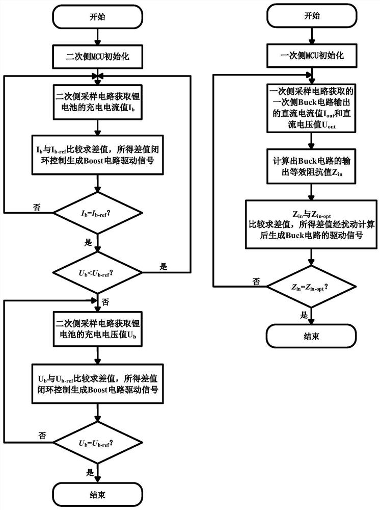
[0082] This embodiment provides a constant current / constant voltage control method for a wireless charging system, see image 3 , is a flowchart of the charging optimization control method of the wireless charging system in the present invention. The method comprises the steps of:

[0083] (1) Initialize the MCU on the primary side and the secondary side, and start the wireless charging system;

[0084] The MCU initialization of the primary side includes the initialization of the given Buck circuit control signal, the given full-bridge inverter control signal and the primary side current / voltage sampling circuit.

[0085] The MCU initialization of the secondary side includes initialization of the given Boost circuit control signal and the current / voltage sampling circuit of the secondary side.

[0086] Specifically, the given parameters determine the DC input voltage source U in , system operating angular frequency ω, primary side transmitting coil inductance L 1 , The equ...


PUM

PropertyMeasurementUnit
inductanceaaaaaaaaaa
Resonant frequencyaaaaaaaaaa

Abstract

The invention discloses a wireless charging system and a constant-current / constant-voltage charging optimization control method, and belongs to the technical field of wireless power transmission. Thewireless charging system is characterized in that the primary side of the system comprises an input power supply, a Buck circuit, a full-bridge inverter, a primary side transmitting coil, a compensating circuit and a primary side MCU, and the secondary side of the system comprises a load, a Boost circuit, a full-wave rectifier, a secondary side receiving coil, a compensation circuit and a secondary side MCU. According to the invention, disturbance control is carried out on the output impedance of the Buck circuit by the primary side system and closed-loop control is carried out on the output current / voltage by the secondary side system, so that the output impedance of the Buck circuit can be stabilized at an optimal output impedance value while the output current / voltage is stabilized neara reference value, accurate control in the constant-current / constant-voltage charging process and optimization of the electric energy transmission efficiency of the system are achieved, and wirelesscommunication is not needed; and the sampling object of the sampling circuit is the direct current quantity, so that the implementation is easy, and the hardware requirement is low.

Description

technical field [0001] The invention relates to a wireless charging system and a control method for constant current / constant voltage charging optimization, belonging to the technical field of wireless power transmission. Background technique [0002] With the development of science and technology, wireless power transmission technology has received more and more attention. Compared with traditional charging technology, wireless charging has the advantages of reliability, safety and convenience. [0003] In wireless charging technology, constant current charging can prevent overcurrent charging during charging, and constant voltage charging can prevent overvoltage charging during charging. Most of the existing constant current and constant voltage charging control is completed through wireless communication. This control method needs to combine the primary side system and the secondary side system for data transmission, but there may be data loss during the wireless communic...

Claims


Application Information

Patent Timeline
Patent Type & Authority Applications(China)
IPC IPC(8): H02J50/12H02J7/00H01M10/44
CPCH02J50/12H02J7/00712H02J7/00714H01M10/44H02J2207/20Y02E60/10
Inventor 卢闻州陈祥修樊启高黄芳辰吴雪峰罗曦陈海英
Owner JIANGNAN UNIV
Why Eureka
Try Eureka