Shoe tree magnetic attraction suspension type shoe sole glue spraying and drying equipment

A drying equipment and hanging technology, which is applied to the field of shoe sole spraying and drying equipment, can solve the problems of affecting the yield, uneven gluing of the upper edge, easy displacement of the upper, etc., to achieve the effect of ensuring the yield

Pending Publication Date: 2021-03-02
广东胜大科技有限公司
View PDF10 Cites 1 Cited by
  • Summary
  • Abstract
  • Description
  • Claims
  • Application Information

AI Technical Summary

Problems solved by technology

[0004] However, this standing automatic gluing machine for shoe uppers adopts a standing setting in which the front of the shoe last faces upwards and the bottom of the shoe last faces the gluing station. When the edge is glued, it is easy to apply glue to the upper, and when the shoe last moves to the gluing station, the upper is also easy to shift, which makes the edge of the upper glue uneven and affects the yield

Method used


Image

  • Shoe tree magnetic attraction suspension type shoe sole glue spraying and drying equipment
  • Shoe tree magnetic attraction suspension type shoe sole glue spraying and drying equipment
  • Shoe tree magnetic attraction suspension type shoe sole glue spraying and drying equipment

Examples


Embodiment 1

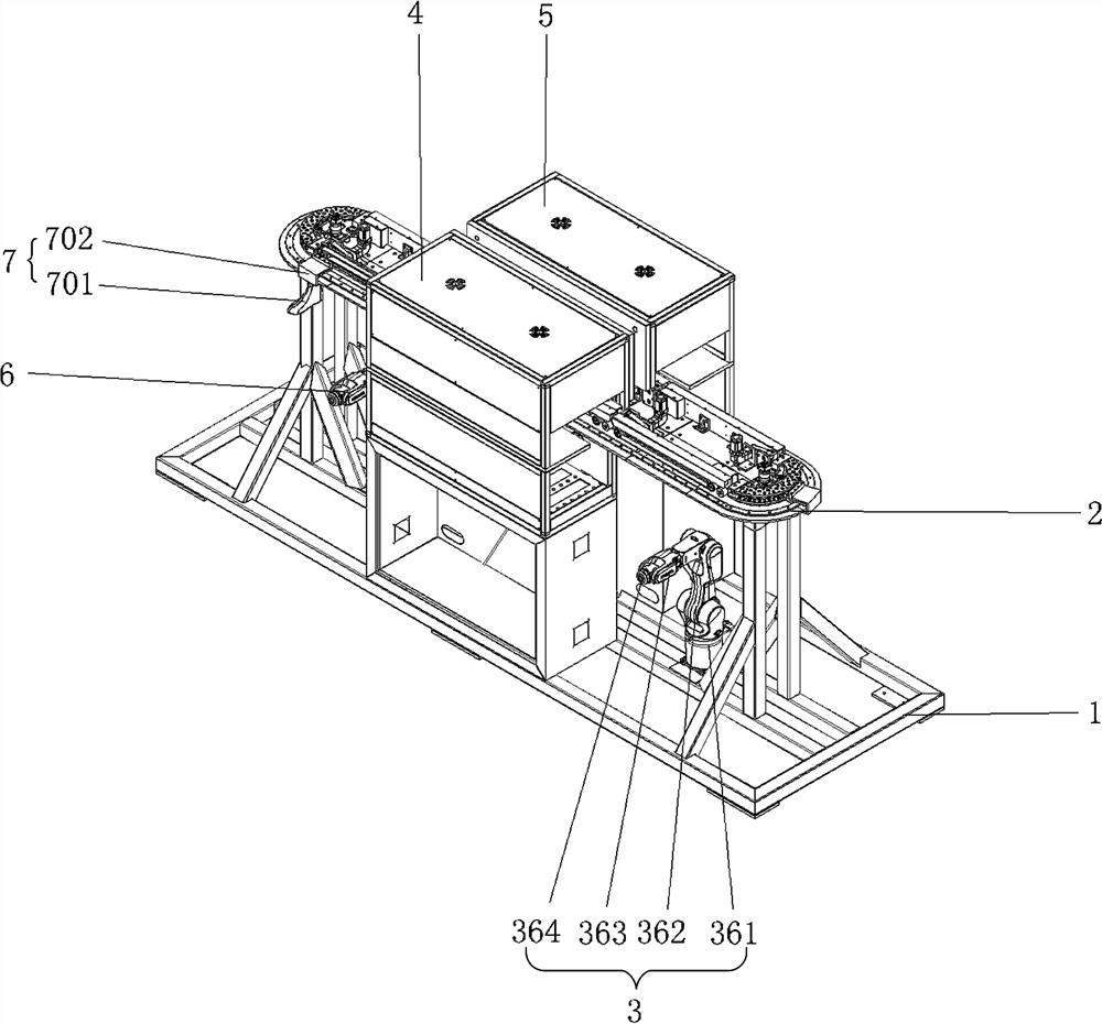
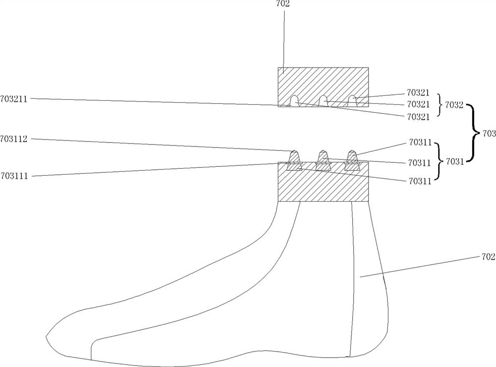
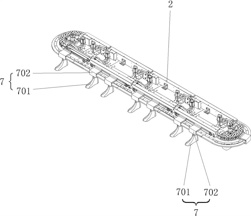
[0030] Such as Figure 1-2 Shown is a shoe last magnetic suction hanging sole glue spray drying equipment, including a frame 1, a conveying device 2, a feeding manipulator 3, a glue spraying device 4, a drying device 5, a feeding manipulator 6 and a plurality of The shoe last positioning device 7, the conveying device 2 is installed on the frame 1, the shoe last positioning device 7 includes a shoe last 701, a shoe last seat 702 and a shoe last hanging positioning device 703, the shoe last seat 702 is arranged on the conveying device 2, the shoe last The last suspension positioning device 703 includes a first magnetic positioning mechanism 7031 and a second magnetic positioning mechanism 7032, the first magnetic positioning mechanism 7031 includes three positioning pins 70311, and each positioning pin 70311 is installed on the top surface of the last opening of the shoe last 701 , and each positioning pin 70311 is perpendicular to the top surface of the last system mouth, one ...

Embodiment 2

[0039] The difference between this embodiment and Embodiment 1 is that: the three positioning pins are all strong magnetic positioning pins; the three pin holes are all pin sleeves made of magnetic metal.

Embodiment 3

[0041]The difference between this embodiment and Embodiment 1 is that the first magnetic positioning mechanism includes three pin holes arranged on the top surface of the shoe last system opening, each pin hole is vertically arranged with the opening facing upwards, and one of the pin holes is formed by The pin sleeve made of strong magnetic metal is embedded in the top surface of the last opening; the second magnetic positioning mechanism includes three positioning pins, and each positioning pin is installed on the lower surface of the shoe last seat. The number of holes is the same and the positions correspond to each other. The positioning pin corresponding to the position of the pin sleeve is made of magnetic metal or a magnet that can attract each other with the pin sleeve; the shoe last seat is matched with the pin hole of the shoe last through the positioning pin , and the latch sleeve and the corresponding positioning pin made of magnetic metal are attracted to each oth...


PUM

PropertyMeasurementUnit
Angleaaaaaaaaaa

Abstract

The invention discloses shoe tree magnetic attraction suspension type shoe sole glue spraying and drying equipment. The equipment comprises a rack, a conveying device, a feeding mechanical arm, a gluespraying device, a drying device, a discharging mechanical arm and a plurality of shoe tree positioning devices, wherein the conveying device, the feeding mechanical arm, the glue spraying device, the drying device and the discharging mechanical arm are installed on the rack; the feeding mechanical arm, the glue spraying device, the drying device and the discharging mechanical arm are sequentially arranged in the conveying direction of the conveying device. The shoe tree positioning device comprises shoe trees, shoe tree bases and shoe tree hanging and positioning devices, the shoe tree basesare arranged on the conveying device, the shoe trees are hung on the shoe tree bases through the corresponding shoe tree hanging and positioning devices respectively, and the shoe tree bottoms of theshoe trees face downwards. According to the shoe tree magnetic attraction suspension type shoe sole glue spraying and drying equipment, a shoe tree can be suspended and positioned below the shoe treebase, a vamp is kept fixed, the edge of the vamp can be accurately glued and dried, and the rate of finished products is guaranteed.

Description

technical field [0001] The invention relates to shoe-making equipment, in particular to a shoe last magnetic suction suspension type shoe sole glue spraying and drying equipment. Background technique [0002] In the shoe manufacturing industry, the sole and the upper are generally produced separately, and then the sole and the upper are bonded together by glue. Therefore, it is necessary to pre-coat a layer of glue on the edge of the upper. It needs to meet a certain width requirement and cannot completely fill the edge of the upper. [0003] At present, the gluing process on the edge of the vamp is usually glued by spraying equipment. For example, the publication date is May 22, 2020, and the publication number is CN210581263U. A standing automatic gluing machine for vamps. The automatic gluing machine includes a frame and a gluing device, the gluing device is installed on the frame, and is characterized in that it also includes an automatic shoe last conveying mechanism; ...

Claims


Application Information

Patent Timeline
IPC IPC(8): A43D25/18A43D25/20A43D95/10A43D117/00
CPCA43D25/183A43D25/20A43D95/10A43D117/00
Inventor 王睦雄
Owner 广东胜大科技有限公司
Why Eureka
Try Eureka