
Internal combustion engine flywheel inclined hole machining equipment

A technology for processing equipment and internal combustion engines, applied in metal processing equipment, drilling/drilling equipment, metal processing, etc., can solve the problems of cumbersome operation, uneven distribution of the inclined hole position of the flywheel, poor fixing effect, etc., to prevent loose effect

Inactive Publication Date: 2021-03-02
安徽万航轨道交通装备有限公司
View PDF6 Cites 4 Cited by
  • Summary
  • Abstract
  • Description
  • Claims
  • Application Information

AI Technical Summary

Problems solved by technology

The invention of patent No. CN2015107083033 discloses a flywheel inclined hole processing device, which includes a tooling platform; a splint, which is erected on the tooling platform, and the splint is provided with a through hole; a positioning platform, which can be lifted by a lifting mechanism. The positioning platform is set on the tooling platform, and the positioning platform is located below the through hole; the positioning platform is provided with a positioning head protruding upward, and the positioning head can be inserted into the center hole of the flywheel to position the flywheel; It is arranged on the splint in a horizontal sliding manner; the slide table is driven to slide by a pushing mechanism; and the drilling head includes a machine base and a drill bit, and the side of the machine base close to the through hole is hinged to the slide table close to the through hole. One side of the hole; although the drilling head of this invention can slide horizontally and adjust the inclination angle, it can be suitable for processing inclined holes on many different types of flywheels, but it has problems in the actual processing of inclined holes on flywheels. The following deficiencies: one, the flywheel slant hole processing device has a poor fixing effect when processing the flywheel, and the flywheel is prone to deviation, resulting in the accuracy of the hole being unable to meet the requirements; second, the slant hole on the flywheel is generally in the form of a ring However, the flywheel slant hole processing device needs to loosen the splint after processing a slant hole, and manually rotate the flywheel. The position of the inclined holes of the flywheel is unevenly distributed

Method used


Image

  • Internal combustion engine flywheel inclined hole machining equipment
  • Internal combustion engine flywheel inclined hole machining equipment
  • Internal combustion engine flywheel inclined hole machining equipment

Examples


Embodiment 1

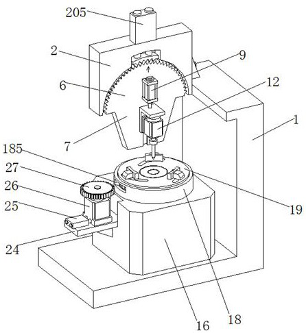
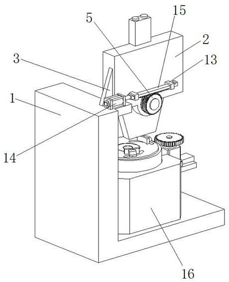
[0035] This embodiment 1 has introduced a kind of flywheel oblique hole processing equipment in the internal combustion engine, refer to the attached figure 1 And attached figure 2 , which includes an L-shaped base 1, the upper end of the L-shaped base 1 is fixedly connected with a vertical plate 2, and a triangular reinforcing rib 3 is also welded at the connection between the L-shaped base 1 and the vertical plate 2, which is used to strengthen the two The stability of the connection between them.

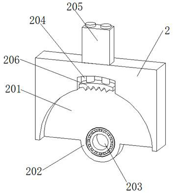
[0036] Reference attached image 3 , attached Figure 4 And attached Figure 5 , a semicircular groove 201 is provided at the lower end of the front side of the vertical plate 2, and a convex block 202 is connected to the center of the semicircular groove 201, and a first bearing 203 is arranged in the convex block 202. A rotating shaft 4 is rotationally connected in the first bearing 203, the rear end of the rotating shaft 4 is connected with the first gear 5, the front end...

Embodiment 2

[0041] Embodiment 2 introduces an improved flywheel oblique hole processing equipment based on Embodiment 1. Its similarities with Embodiment 1 will not be described again. For the differences, refer to the attached figure 1 , attached image 3 And attached Figure 4 .

[0042] In Embodiment 2, an arc-shaped tooth surface 601 is provided on the arc-shaped outer surface of the semi-circular loading plate 6 , and a receiving groove 204 is opened at the top of the semi-circular groove 201 . On the vertical plate 2 above the receiving groove 204, a third cylinder 205 is fixed, and the piston rod of the third cylinder 205 stretches into the lower end of the receiving groove 204 to be connected with an arc bead 206, and on the lower surface of the arc bead 206 There are occlusal teeth (not marked in the figure); by pressing down the arc-shaped bead 206, the occlusal teeth are engaged with the arc-shaped tooth surface 601 on the semicircular loading plate 6, so that the semicircula...


PUM


Abstract

The invention relates to the technical field of flywheel machining equipment, and particularly discloses internal combustion engine flywheel inclined hole machining equipment. The internal combustionengine flywheel inclined hole machining equipment comprises an L-shaped base, a vertical plate is fixedly connected to the upper end of the L-shaped base, a first gear is connected to the rear end ofa rotating shaft, a semicircular loading plate arranged in a semicircular groove is connected to the front end of the rotating shaft, an extension plate is connected to the lower end of the semicircular loading plate, and vertical limiting sliding grooves are formed in the semicircular loading plate and the extension plate; and a hydraulic cylinder is fixed to the middle of the upper end of the front side face of the semicircular loading plate, the lower end of the hydraulic cylinder is connected with a sliding base, and a drilling motor is fixed in the sliding base. According to the whole flywheel inclined hole machining equipment, a flywheel can be firmly clamped before drilling machining is conducted on the flywheel, loosening in the machining process is prevented, and meanwhile the drilling inclined angle can be accurately adjusted through stretching or retracting of the first air cylinder; and in addition, inclined hole machining can be continuously carried out on different partsof the flywheel through a driving motor, and the flywheel inclined hole machining equipment is higher in machining efficiency and machining precision.

Description

technical field [0001] The invention relates to the technical field of flywheel processing equipment, and specifically discloses a flywheel inclined hole processing equipment in an internal combustion engine. Background technique [0002] The internal combustion engine is a kind of power machinery, which is a heat engine that directly converts the heat energy released into power by burning fuel inside the machine. The flywheel is a disc-shaped part with a large moment of inertia, and its function is like an energy storage. Its main function in the internal combustion engine is to store a part of the energy transmitted to the crankshaft during the power stroke, so as to overcome resistance in other strokes. Drive the crank rod mechanism to cross the upper and lower dead centers to ensure that the rotational angular velocity and output torque of the crankshaft are as uniform as possible, and make it possible for the internal combustion engine to overcome short-term overload. ...

Claims


Application Information

Patent Timeline
Patent Type & Authority Applications(China)
IPC IPC(8): B23B41/00B23B47/00B23Q3/08B23Q5/10B23Q5/26B23Q15/26
CPCB23B41/00B23B47/00B23Q3/08B23Q5/10B23Q5/26B23Q15/26
Inventor 陶亚青黄韬黄全贵邰飞
Owner 安徽万航轨道交通装备有限公司
Learn More