

Auxiliary device for improving rudder blade machining precision
A technology of processing accuracy and auxiliary devices, applied in positioning devices, metal processing equipment, metal processing machinery parts, etc., can solve the problems of high operating intensity, low speed, unsuitable for rudder blade taper hole processing and alignment, etc., to prevent shaking Offset, the effect of reducing machining accuracy
- Summary
- Abstract
- Description
- Claims
- Application Information
AI Technical Summary
Problems solved by technology
Method used
Image

Examples
Embodiment 1
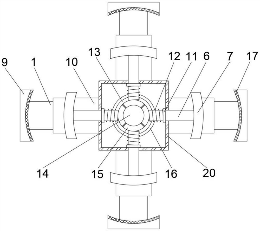
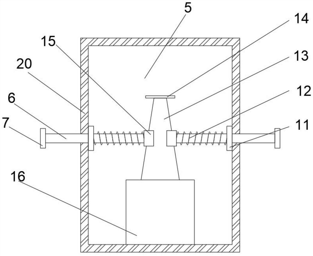
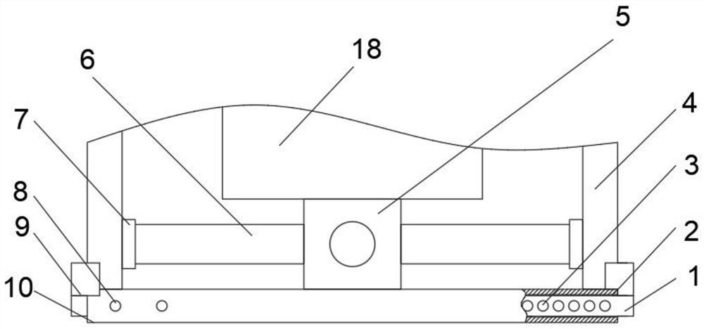
[0024] see Figure 1-3 , an auxiliary device for improving the machining accuracy of rudder blades, comprising a cross plate 10, the top of the cross plate 10 is fixedly connected with a telescopic alignment device 5, and the telescopic alignment device 5 includes a box body 20, and the box body 20 The inner bottom of the cylinder is fixedly connected with a cylinder 16, and the top of the cylinder 16 is fixedly connected with a slide bar 13. The shape of the slide bar 13 is a circular truncated shape, and the side with a larger bottom area of the slide bar 13 is fixedly connected with the cylinder 16. The top of the sliding rod 13 is fixedly connected with a baffle plate 14, and the four sides of the outer wall of the box body 20 are all slidably connected with a telescopic rod 6, and one end of the telescopic rod 6 located inside the box body 20 is fixedly connected with a slider 15, The slide block 15 is slidably connected with the slide bar 13, the end of the telescopic ...
Embodiment 2
[0028] On the basis of Embodiment 1, due to the sliding connection between the telescopic rod 6 and the box body 20, when the device is installed, as long as it is tilted, the telescopic rod 6 will slide out of the box body 20, making installation inconvenient , and the extrusion plate 7 will also hit the chuck 9. After a long time of use, the alignment accuracy will decrease, which will affect the machining accuracy of the taper hole. In order to improve it, the following design is made. The inner wall of the box 20 is uniform The fixed plate 11 is welded, and the slide block 15 passes through the fixed plate 11. The telescopic rod 6 is covered with a compression spring 12, and the two ends of the compression spring 12 are respectively fixed on the slide block 15 and the fixed plate 11. The compression spring 12 Squeeze the slider 15, so that the slider 15 is always close to the slide rod 13, prevents it from tilting and sliding out, and is convenient for installation. At the ...
PUM
 Abstract
Description
Claims
Application Information