
Diamond grinding block and manufacturing method thereof

A technology of diamond and grinding blocks, which is applied in the field of diamond grinding blocks and its production. It can solve the problems of difficult cutting of abrasives, clogging of screws and nuts, and low processing efficiency, and achieve the effects of convenient assembly and replacement, reliability assurance and convenient processing.

Pending Publication Date: 2021-03-02
广东奔朗新材料股份有限公司
View PDF0 Cites 1 Cited by
  • Summary
  • Abstract
  • Description
  • Claims
  • Application Information

AI Technical Summary

Problems solved by technology

[0002] Most of the metal-bonded diamond grinding blocks currently on the market use iron-copper alloy powder as the aggregate, copper-tin alloy powder or simple tin and zinc metal powder as the binder. Abrasives are not easy to edge out, and the processing efficiency is low.
Moreover, the current assembly structure of conventional diamond grinding blocks is locked with screws and nuts, that is, the connection between the abrasive cutter head and the base is threaded. This connection method, when working with a large amount of grinding, is not stable due to vibration. It will cause loosening of screws and nuts, which will affect the quality and efficiency of grinding; at the same time, the debris and mud generated during the grinding process will block the screws and nuts, making it difficult to disassemble the abrasive cutter head and base, and difficult to reuse

Method used


Image

  • Diamond grinding block and manufacturing method thereof
  • Diamond grinding block and manufacturing method thereof
  • Diamond grinding block and manufacturing method thereof

Examples


Embodiment Construction

[0025] In order to facilitate the understanding of the present invention, the present invention will be described more fully below with reference to the associated drawings. Preferred embodiments of the invention are shown in the accompanying drawings. However, the present invention can be embodied in many different forms and is not limited to the embodiments described herein. On the contrary, these embodiments are provided to make the understanding of the disclosure of the present invention more thorough and comprehensive.

[0026] It should be noted that when an element is referred to as being “fixed” to another element, it can be directly on the other element or there can also be an intervening element. When an element is referred to as being "connected to" another element, it can be directly connected to the other element or intervening elements may also be present. The terms "vertical," "horizontal," "left," "right," and similar expressions are used herein for purposes ...


PUM


Abstract

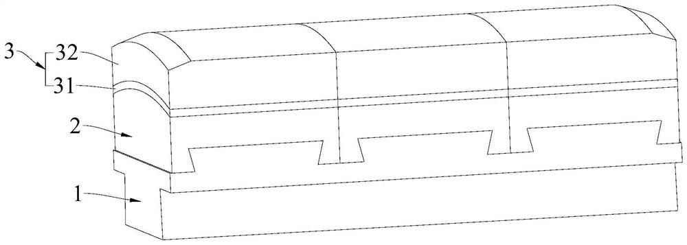
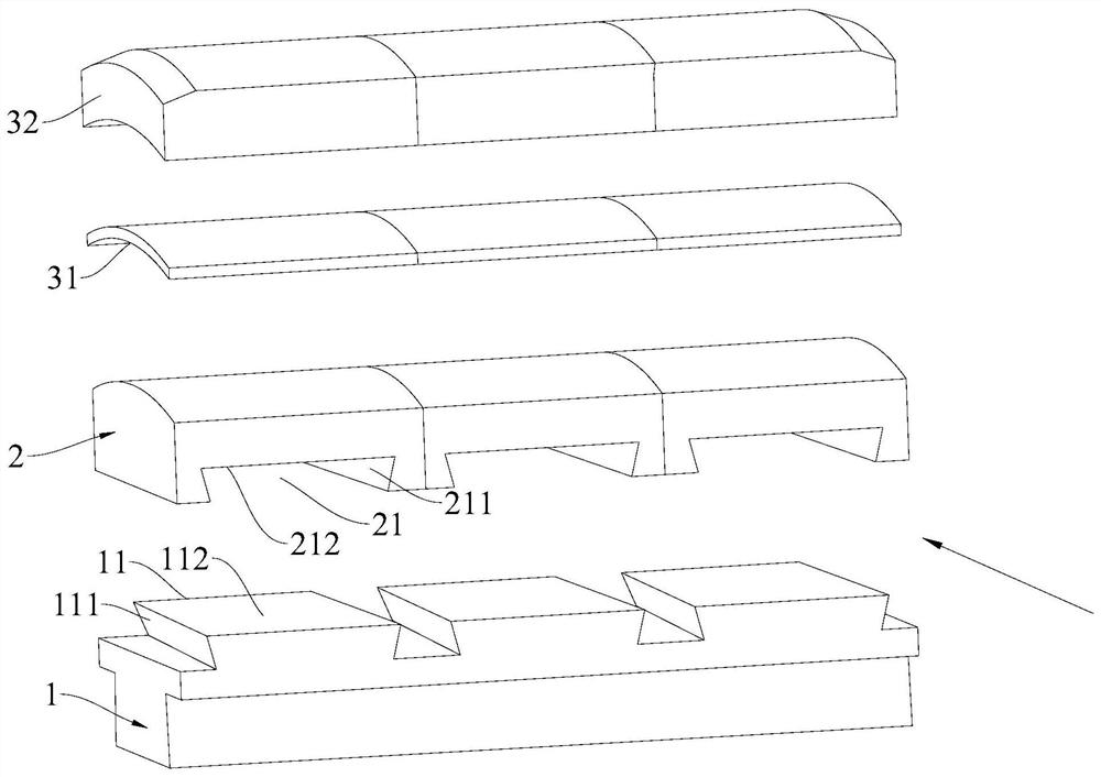
The invention discloses a diamond grinding block and a manufacturing method thereof. The diamond grinding block comprises a clamping seat, a base body and a tool bit; the tool bit is bonded to the upper surface of the base body, and a groove is formed in the lower surface of the base body; a protruding block is arranged on the upper surface of the clamping seat; the protruding block is provided with two oppositely-arranged first side faces, and the first side faces incline towards the protruding block from top to bottom and incline towards the protruding block from front to back; and the groove is provided with two opposite second side faces, the protruding block is suitable for being assembled in the groove, and the first side faces are suitable for abutting against the second side faces.A method for manufacturing the diamond grinding block comprises the following steps of evenly mixing powder of a transition layer and powder of a working layer; putting the base body, the transitionlayer and the working layer into a mold cavity of a mold according to a sequence or a reverse sequence; placing the mold on a hot press to complete bonding of the tool bit and the base body; releasingthe mold; and assembling the base body bonded with the tool bit on the clamping seat. The diamond grinding block has the advantages that the production process is simple, the mounting and dismountingare convenient, the clamping base can be repeatedly used and the diamond grinding block is economical and environmentally friendly.

Description

technical field [0001] The invention relates to the technical field of polishing abrasive tools, in particular to a diamond grinding block and a manufacturing method thereof. Background technique [0002] Most of the metal-bonded diamond grinding blocks currently on the market use iron-copper alloy powder as the aggregate, copper-tin alloy powder or simple tin and zinc metal powder as the binder. Abrasives are not easy to produce edges, and the processing efficiency is low. Moreover, the current assembly structure of conventional diamond grinding blocks is locked with screws and nuts, that is, the connection between the abrasive cutter head and the base is threaded. This connection method, when working with a large amount of grinding, is not stable due to vibration. It will cause loosening of screws and nuts, which will affect the quality and efficiency of grinding; at the same time, the debris and mud generated during the grinding process will block the screws and nuts, ma...

Claims


Application Information

Patent Timeline
Patent Type & Authority Applications(China)
IPC IPC(8): B24D18/00
CPCB24D18/0009
Inventor 彭凯马邵伟张立程彦强魏菊娄晶
Owner 广东奔朗新材料股份有限公司
Learn More