A water conservancy decontamination machine based on computer control

A computer and decontamination machine technology, applied in the field of water conservancy decontamination machines, can solve the problem of single function of water conservancy garbage recycling equipment, and achieve the effect of good effect and sufficient garbage combustion.

Active Publication Date: 2021-11-12
天津万联高新科技有限公司
View PDF5 Cites 0 Cited by
  • Summary
  • Abstract
  • Description
  • Claims
  • Application Information

AI Technical Summary

Problems solved by technology

[0004] The purpose of the present invention is to solve the problem of the single function of water conservancy waste recycling equipment in the prior art, and propose a water conservancy decontamination machine based on computer control

Method used


Image

  • A water conservancy decontamination machine based on computer control
  • A water conservancy decontamination machine based on computer control
  • A water conservancy decontamination machine based on computer control

Examples


Embodiment 1

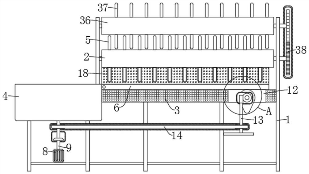
[0031] refer to Figure 1-5 , a water conservancy decontamination machine based on computer control, comprising a support frame 1, the upper end of the support frame 1 is fixedly installed with a hollow conveyor belt 2 arranged obliquely, and the outer wall of the hollow conveyor belt 2 is fixedly equipped with a plurality of evenly distributed conveyor rods 5 The side wall of the support frame 1 is fixedly equipped with an incineration cylinder 4, the side wall of the incineration cylinder 4 is fixedly equipped with a lower hollow plate 3, and the upper end of the lower hollow plate 3 is provided with an upper hollow that is rotatably connected with the side wall of the incineration cylinder 4. Plate 6, the upper hollow plate 6 corresponds to the position of the hollow conveyor belt 2, an igniter 7 is fixedly installed on the inner wall of the incineration cylinder 4, a motor 8 is fixedly installed on the lower end of the incineration cylinder 4, and the rotating shaft 9 of th...

Embodiment 2

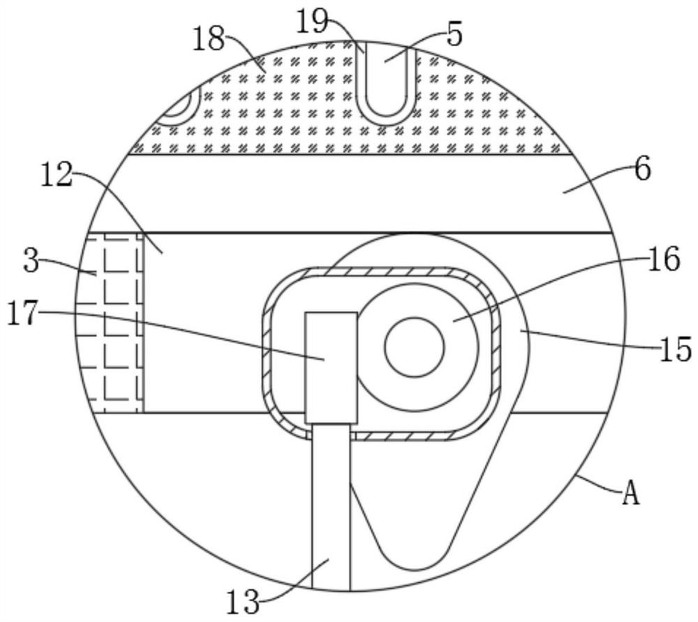
[0036] refer to figure 1 , image 3 and Figure 5 , is basically the same as Embodiment 1, furthermore: the feeding mechanism includes a cam 15 that is rotatably connected in the device groove 12, the side wall of the cam 15 is against the lower end side wall of the upper hollow plate 6, and the side wall of the cam 15 is fixedly connected There is a worm wheel 16, the lower end of the device groove 12 is provided with a rotating rod 13 fixedly connected with the support frame 1, the upper end of the rotating rod 13 is fixedly connected with a worm screw 17 meshing with the worm wheel 16, the lower end of the rotating rod 13 and the rotating shaft 9 pass through the first A chain transmission 14 is connected, and the motor 8 drives the rotary rod 13 to rotate through the first chain transmission 14, and the rotary rod 13 drives the cam 15 to rotate through the worm 17 and the worm wheel 16, and the cam 15 will intermittently lift the upper hollow plate 6 up, and the upper Th...

Embodiment 3

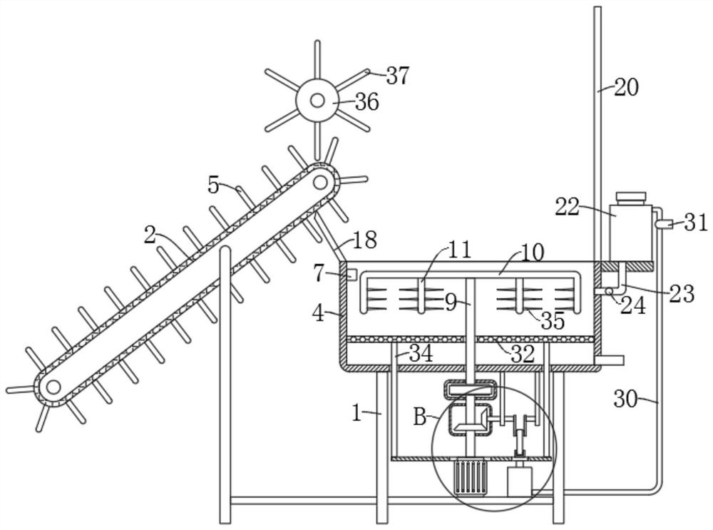
[0039] refer to figure 2 and Figure 4 , is basically the same as Embodiment 1, furthermore: the combustion-supporting mechanism includes a fuel tank 22 fixedly installed on the side wall of the upper end of the incineration cylinder 4, and the lower end of the fuel tank 22 is provided with a fuel injection pipe 23 extending into the incineration cylinder 4. A solenoid valve 24 is fixedly installed in the oil pipe 23, and a pressurizing mechanism connected to the fuel injection pipe 23 is provided at the lower end of the incineration cylinder 4. During the incineration process, the solenoid valve 24 is opened, and the combustion accelerant in the fuel tank 22 can be injected into the combustion chamber. Pipe 23 is sprayed in the incineration cylinder 4, and rubbish is burned more fully, and the pressurization mechanism can make the combustion-supporting agent injection in the oil tank 22 more even.

[0040] Furthermore, the pressurizing mechanism includes an inflator 25 fixe...


PUM


Abstract

The invention discloses a water conservancy decontamination machine based on computer control, which belongs to the field of water conservancy engineering. A water conservancy decontamination machine based on computer control, including a support frame, the upper end of the support frame is fixedly equipped with a hollow conveyor belt arranged obliquely, the outer wall of the hollow conveyor belt is fixedly equipped with a plurality of uniformly distributed conveyor rods, and the side wall of the support frame The incineration cylinder is fixedly installed, the side wall of the incineration cylinder is fixedly equipped with a lower hollow plate, the upper end of the lower hollow plate is provided with an upper hollow plate that is rotatably connected with the side wall of the incineration cylinder, and the lower end of the incineration cylinder is fixedly installed with a motor. The rotating shaft of the motor extends to the incineration cylinder and is fixedly connected with a cross bar. The lower end of the cross bar is fixedly connected with a plurality of stirring paddles. The side wall of the cylinder is provided with a combustion-supporting mechanism; the invention can recover river waste and incinerate the waste at the same time, has complete functions and does not need to be loaded and checked, and is more convenient to use.

Description

technical field [0001] The invention relates to the technical field of water conservancy engineering, in particular to a water conservancy decontamination machine based on computer control. Background technique [0002] Water conservancy projects are projects built to control and allocate natural surface water and groundwater to achieve the purpose of eliminating harm and rejuvenating profits. Also known as water engineering. Water is an indispensable precious resource for human production and life, but its natural state does not fully meet human needs. Only by building water conservancy projects can we control water flow, prevent floods, and regulate and distribute water to meet the needs of people's life and production for water resources. [0003] It is found in daily life that there are often some garbage floating in the river, so people will use computer-controlled garbage recycling equipment to recycle the floating garbage, but the existing garbage recycling equipmen...

Claims


Application Information

Patent Timeline
Patent Type & Authority Patents(China)
IPC IPC(8): E02B15/10B01D35/02
CPCB01D35/02E02B15/10E02B15/104
Inventor 吕欣
Owner 天津万联高新科技有限公司
Why Eureka
Try Eureka