Cantilever beam electric field detection device

A technology of detection device and cantilever beam, applied in the field of electric field detection, can solve the problem of low sensitivity

Inactive Publication Date: 2021-03-02
彭彦莉
View PDF0 Cites 0 Cited by
  • Summary
  • Abstract
  • Description
  • Claims
  • Application Information

AI Technical Summary

Problems solved by technology

The sensitivity of traditional electric field measurement devices is low, and it is of great significance to explore

Method used


Image

  • Cantilever beam electric field detection device
  • Cantilever beam electric field detection device
  • Cantilever beam electric field detection device

Examples


Embodiment 1

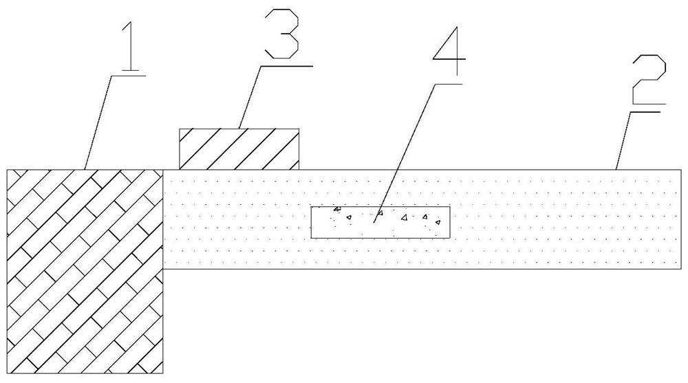
[0022] The invention provides a cantilever beam electric field detection device. like figure 1 As shown, the cantilever beam electric field detection device includes a vibration source 1, a cantilever beam 2, a piezoelectric material block 3, a cavity 4, and an organic conjugated polymer material. The cantilever beam 2 is fixed on the vibration source 1 . The material of the cantilever beam 2 is aluminum alloy, silicon, semiconductor material, diamond. The piezoelectric material block 3 is arranged on the top surface of the cantilever beam 2 near the fixed end, and the piezoelectric material block 3 is connected to an external circuit. The piezoelectric material block 3 is made of piezoelectric ceramics or polyvinylidene fluoride. A cavity 4 is arranged in the cantilever beam 2 , and the organic conjugated polymer material fills the cavity 4 . The organic conjugated polymer material is poly-3-hexylthiophene. When heated, the microscopic morphology of poly-3-hexylthiophene...

Embodiment 2

[0025] On the basis of Example 1, such as figure 2 As shown, the number of cavities 4 is two. The two cavities 4 are parallel. Specifically, the direction of the line connecting the two cavities 4 is perpendicular to the direction of the cantilever beam 2 . In this way, when the molecular chain direction of the organic conjugated polymer material changes, the stress in the cantilever beam 2 changes more, thereby changing the resonant frequency of the cantilever beam 2 more, thereby achieving higher sensitivity electric field detection.

Embodiment 3

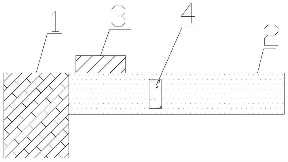
[0027] On the basis of Example 1, such as image 3 As shown, the cavity 4 is a cuboid. The long side of the cavity 4 is perpendicular to the direction of the cantilever beam 2 . The length of the long sides of the cuboid is greater than 1 / 2 of the thickness of the cantilever beam 2 . Since the cantilever beam 2 is driven by the fixed end to vibrate, along the direction of the cantilever beam 2, the force of adjacent structural units has a serious impact on the resonant frequency of the cantilever beam 2. Therefore, along the direction of the cantilever beam 2, the force between adjacent structural units A change in the applied force will severely change the resonant frequency of the cantilever beam 2 . In this embodiment, the long side of the cuboid is perpendicular to the direction of the cantilever beam 2, and the length of the long side of the cuboid is greater than that of the cantilever beam 2 at image 3 In this way, the molecular chain direction of the organic conjug...


PUM


Abstract

The invention provides a cantilever beam electric field detection device. The cantilever beam electric field detection device comprises a vibration source, a cantilever beam, a piezoelectric materialblock, a cavity and an organic conjugated polymer material, the cantilever beam is fixed on the vibration source, the piezoelectric material block is arranged on the top surface of the cantilever beamand close to the fixed end, the piezoelectric material block is connected with an external circuit, the cavity is arranged in the cantilever beam, and the cavity is filled with the organic conjugatedpolymer material. The device has the advantage of high electric field measurement sensitivity.

Description

technical field [0001] The invention relates to the field of electric field detection, in particular to a cantilever beam electric field detection device. Background technique [0002] The measurement of the electric field is not only of great significance to the launch of missiles, rockets, and aircrafts, but also to places on the ground that are prone to static electricity and are easily harmed by static electricity and radar, such as urban environmental pollution, ultra-clean laboratories, oil refineries, and oil storage stations. Applications. The sensitivity of traditional electric field measurement devices is low, and it is of great significance to explore electric field detection technology based on new principles to improve the sensitivity of electric field measurement. Contents of the invention [0003] In order to solve the above problems, the present invention provides a cantilever beam electric field detection device, including: a vibration source, a cantileve...

Claims


Application Information

Patent Timeline
IPC IPC(8): G01R29/12G01R29/22
CPCG01R29/12G01R29/22
Inventor 不公告发明人
Owner 彭彦莉
Why Eureka
Try Eureka