Station building environment intelligent control system

A technology of intelligent control system and intelligent control unit, which is applied in general control system, control/adjustment system, program control, etc., can solve the problems of manpower and material resources consumption, filter clogging, troublesome going to the site, etc., so as to reduce labor costs, reduce Operation and maintenance costs and the effect of extending the maintenance cycle

Pending Publication Date: 2021-03-02
广州尚广环保科技有限公司
0 Cites 0 Cited by

AI-Extracted Technical Summary

Problems solved by technology

[0003] However, due to the large particles directly collected from the river and the frequent filtration cycles, it is easy to cause the filter to be clogged. This requires the operation and maintenance personnel to frequently clean the filter impurities and replace the filter, which cannot meet the requirements of...

Abstract

The invention relates to the technical field of water quality monitoring, in particular to a station building environment intelligent control system. The invention aims to solve the technical problemsthat equipment is inconvenient to replace and maintenance is very troublesome. In order to solve the technical problem, the invention provides the station building environment intelligent control system, and the station building environment intelligent control system is composed of a water sampling unit, a water sample pretreatment unit, an automatic fault alarm unit, an automatic cleaning unit,an intelligent control unit and a data acquisition unit. Applying the station building environment intelligent control system has the advantages that fault components can be detected through the faultautomatic alarm device, the backup device can be automatically switched, and the system can be automatically controlled through the intelligent control unit to achieve automatic pipeline reverse cleaning and automatic water collection. A series of physical reactions can be fully automatically realized by controlling a main process through a PLC after the treatment of the steps, so that particulate matters in the water body are filtered, and a measuring instrument is provided for monitoring the water quality.

Application Domain

Technology Topic

Image

  • Station building environment intelligent control system
  • Station building environment intelligent control system
  • Station building environment intelligent control system

Examples

  • Experimental program(1)

Example Embodiment

[0022]The technical solutions in the embodiments of the present invention will be clearly and completely described below in conjunction with the accompanying drawings in the embodiments of the present invention. Obviously, the described embodiments are only a part of the embodiments of the present invention, rather than all the embodiments. Based on the embodiments of the present invention, all other embodiments obtained by those of ordinary skill in the art without creative work shall fall within the protection scope of the present invention.
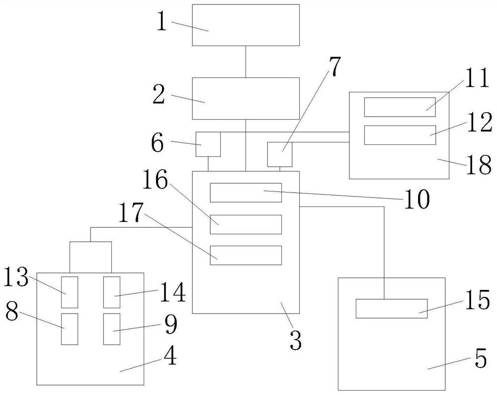
[0023]SeeFigure 1-5, An embodiment provided by the present invention: a station environment intelligent control system, including a water sampling unit 4, a water sample pretreatment unit 3, an automatic fault alarm unit, an automatic cleaning unit 5, an intelligent control unit 2 and a data acquisition unit 1. The water collection unit 4 is electrically connected to the intelligent control unit 2, the automatic cleaning unit 5 is electrically connected to the intelligent control unit 2, and the intelligent control unit 2 is electrically connected to the data collection unit 1 The intelligent control unit 2 is electrically connected to the solenoid valve, the electric ball valve, the first submersible pump 8, the second submersible pump 9, the first peristaltic pump 6 and the second peristaltic pump 7.
[0024]Specifically, the water collection unit 4 is electrically connected to the intelligent control unit 2 through a wire, and the water collection unit 4 is provided with a first sampling valve 13 and a second sampling valve 14.
[0025]Specifically, after the water sample pretreatment unit 3 undergoes physical precipitation, it is filtered through the ceramic filter plate 10 to the sample water cup 18.
[0026]Specifically, the automatic fault alarm unit is electrically connected to the intelligent control unit 2 through a signal line.
[0027]Specifically, the automatic cleaning unit 5 is electrically connected to the intelligent control unit 2, and the automatic cleaning unit 5 is provided with a tap water valve 15.
[0028]Specifically, the data acquisition unit 1 is an industrial computer with visible processes, visible data, settable parameters, and controllable functions.
[0029]Specifically, the intelligent control unit 2 is a programmable controller PLC.
[0030]Specifically, the intelligent control unit 2 is provided with an electric control cabinet, the electric control cabinet is provided with a connecting circuit, and the connecting circuit includes a programmable controller PLC, an intermediate relay, a surge protector, a 24v switching power supply, and a current contact. The external 220v power supply is connected to the L and N terminals of the air switch, and is grounded to the PE terminal of the surge protector. The air switch L and N terminals are grounded. It is connected to a 24v switching power supply, the 24v switching power supply V+, V- is connected to a programmable controller PLC, the programmable controller PLC is connected to an intermediate relay, the intermediate relay is connected to a wiring terminal, and the programmable controller The PLC is connected with the signal converter and the voltage transmitter, and the voltage transmitter, the signal converter and the terminal are electrically connected.
[0031]Specifically, the pretreatment unit is an integrated tank made of stainless steel, and the integrated tank contains two ceramic plates, a liquid level sensor 16, a first liquid level switch 11, and a second liquid level switch 17.
[0032]Specifically, the integrated tank of the pretreatment unit is connected to the integrated tank through the first peristaltic pump 6 and the second peristaltic pump 7 after precipitation.
[0033]Working principle: In order to reduce labor costs and time spent on going to the site, reduce equipment maintenance costs, and liberate operation and maintenance personnel, the present invention is an intelligent control system for the station environment without manual involvement. Specifically, in the embodiment of the station room environment intelligent control system of the present invention, the structure diagram of the station room environment intelligent control system is as follows:figure 1 Shown.figure 1 In, the station environment intelligent control system includes a water collection unit 4, a water sample pretreatment unit 3, an automatic fault alarm unit, an automatic cleaning unit 5, an intelligent control unit 2, and a data acquisition unit 1. The data acquisition unit 1 is connected to the intelligent control unit 2 through Ethernet communication, the water collection unit 4 is connected to the intelligent control unit 2, the water sample pretreatment unit 3 is connected to the water collection unit 4, and the automatic cleaning unit 5 is connected to the intelligent control unit 2. The ceramic filter plate 10 is connected to one end of the first peristaltic pump 6 and the second peristaltic pump 7 through the No. 8 trachea, and the sample water cup 18 is connected to the other end of the first peristaltic pump 6 and the second peristaltic pump 7 through the No. 8 trachea. The first liquid level The switch 11 and the second liquid level switch 17 are connected to the intermediate relay in the intelligent control unit 2 through wires, the first submersible pump 8 and the second submersible pump 9 are connected to the AC contactor in the intelligent control unit 2 through wires, and the first sampling valve 13 And the second sampling valve 14 are connected to the intermediate relay of the intelligent control unit 2 through wires, the first peristaltic pump 6 and the second peristaltic pump 7 are connected to the intermediate relay in the intelligent control unit 2 through wires, and the water valve 15 is connected to the intelligent control unit 2 through wires. The liquid level sensor 16 is connected to the signal converter in the intelligent control unit 2 through a signal line, and the mixer 12 is connected to the intermediate relay in the intelligent control unit 2 through a wire.
[0034]The station environment intelligent control system reduces labor costs and time spent on site, and reduces equipment maintenance costs. The entire process does not require manual involvement. The on-site operation and maintenance time of on-site equipment can be increased from the original 7 days to 1 month. , Greatly extend the cycle of manual on-site maintenance, which can meet the requirement of manual maintenance for water quality online monitoring stations for one month or more.
[0035]In this embodiment, the intelligent control unit 2 is provided with a control circuit, and a power supply circuit is provided on the control circuit. The circuit principle diagram of the power supply circuit is as follows:figure 2 ,image 3 ,Figure 4 ,Figure 5 Shown. infigure 2 ,image 3 ,Figure 4 ,Figure 5 It includes programmable control PLC, intermediate relay KM, AC contactor CJ, air switch QF, surge protector SPD, 24v switching power supply 1U, signal converter T, voltage transmitter SP, solenoid valve SV, submersible pump, Mixer 12M liquid level switch, liquid level sensor 16, voltage sensor, etc. The two ends of 220v alternating current L and N are connected to the two ends of the system main switch QF, the PE end is connected to the PE end of the surge protector, and the two ends of the air switch QF are connected to the two ends of the air switch QF1-QF4 respectively. The two ends of QF4 are connected to the 24v switching power supply L and N, the 24v switching power supply v+, v- is connected to PLCv+, v-, the PLC output Q point is connected to the intermediate relay KM v+, and the intermediate relay V- is connected to the 24 switching power supply v- . The two ends of the air switch QF3L and N are respectively connected to the two ends of the solenoid valve L and N through the intermediate relay KM normally open (where the L line is connected through the input end of the voltage transmitter SP, and then the output end is connected to the solenoid valve). Air switches QF1, QF2 L, N are interlocked with KM12, KM13 normally open and normally closed respectively, and then connected to AC contactors CJ1, CJ2 L, N through KM12, KM13 normally open, air switches QF1, QF2 L The two ends of N and N are respectively connected to the submersible pump through the AC contactors CJ1 and CJ2 normally open (where the L line passes through the input end of the voltage transmitter SP, and then the output end is connected to the submersible pump).
[0036]In this embodiment, the voltage transmitter SP detects the L line current value input of the corresponding component, and the output terminal 0-10V is connected to the programmable controller PLC AI module. The high liquid level ends of the liquid level switch are respectively connected to the programmable controller PLC I point and the 24v switching power supply V+, and the low liquid level ends of the liquid level switch are respectively connected to the programmable controller PLC I point and the 24v switching power supply V+. The two ends of the liquid level sensor 16 and the pressure sensor are respectively connected to the input end of the signal converter T, and the output end of the signal converter is respectively connected to the programmable controller PLC AI module.
[0037]In this embodiment, the data acquisition unit 1 is connected to the intelligent control unit 2 through a network cable, and the internal variables and analog parameters of the programmable controller PLC in the intelligent control unit 2 can be collected. The buttons can be set on the industrial computer screen to start control and parameters. Display, dynamic flow animation display, etc.
[0038]In short, in the intelligent control system for the station room environment of the present invention, no manual participation is required. The present invention can reduce labor costs and time spent on site visits, reduce equipment operation and maintenance costs, and greatly extend the manual on-site maintenance cycle.
[0039]In the description of the present invention, it should be understood that the terms "center", "middle", "off-center", "longitudinal", "transverse", "length", "width", "thickness", "height", "Up", "Down", "Front", "Back", "Left", "Right", "Vertical", "Horizontal", "Top", "Bottom", "Inner", "Outer", "Shun" The orientation or positional relationship indicated by "clockwise", "counterclockwise", "axial", "radial", "circumferential", etc. is based on the orientation or positional relationship shown in the drawings, and is only for the convenience of describing and simplifying the present invention. The description does not indicate or imply that the pointed device or element must have a specific orientation, be constructed and operated in a specific orientation, and therefore cannot be understood as a limitation of the present invention.
[0040]For those skilled in the art, it is obvious that the present invention is not limited to the details of the foregoing exemplary embodiments, and the present invention can be implemented in other specific forms without departing from the spirit or basic characteristics of the present invention. Therefore, from any point of view, the embodiments should be regarded as exemplary and non-restrictive. The scope of the present invention is defined by the appended claims rather than the above description, and therefore it is intended to fall within the claims. All changes within the meaning and scope of the equivalent elements of are included in the present invention. Any reference signs in the claims should not be regarded as limiting the claims involved.

PUM

no PUM

Description & Claims & Application Information

We can also present the details of the Description, Claims and Application information to help users get a comprehensive understanding of the technical details of the patent, such as background art, summary of invention, brief description of drawings, description of embodiments, and other original content. On the other hand, users can also determine the specific scope of protection of the technology through the list of claims; as well as understand the changes in the life cycle of the technology with the presentation of the patent timeline. Login to view more.

Similar technology patents

Method for preparing saffron tea and product

Owner:浙江六江源绿色食品有限公司

Classification and recommendation of technical efficacy words

  • Reduce operation and maintenance costs
  • Save labor costs

Food residue disposal

Owner:SUZHOU SHIHAO BUILDING MATERIAL NEW TECH ENG
Why Eureka
Try Eureka