Aerial survey method and system based on real-time dense three-dimensional point cloud of unmanned aerial vehicle and DSM

A 3D point cloud and UAV technology, applied in 3D modeling, computer parts, character and pattern recognition, etc., can solve the problems of general accuracy and high GPS requirements, and achieve low cost, fast speed and rich output content Effect

Pending Publication Date: 2021-03-02
西安视野慧图智能科技有限公司
View PDF4 Cites 13 Cited by
  • Summary
  • Abstract
  • Description
  • Claims
  • Application Information

AI Technical Summary

Problems solved by technology

This method is fast, but the accuracy is average, and the requirements for GPS are relatively high, such as the patent CN201880073770.5

Method used


Image

  • Aerial survey method and system based on real-time dense three-dimensional point cloud of unmanned aerial vehicle and DSM
  • Aerial survey method and system based on real-time dense three-dimensional point cloud of unmanned aerial vehicle and DSM
  • Aerial survey method and system based on real-time dense three-dimensional point cloud of unmanned aerial vehicle and DSM

Examples


Embodiment 1

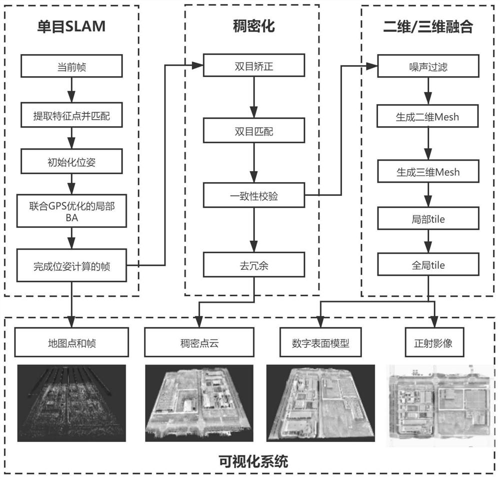
[0079] An aerial survey method based on UAV real-time dense 3D point cloud and DSM, see figure 1 , including the following steps:

[0080] S1: Obtain the original image captured by the camera during the flight of the drone, and use SLAM technology to estimate the camera pose of the original image; specifically include:

[0081] S11: Read the camera type corresponding to the camera in the drone from the preset camera calibration library, obtain a distortion parameter, and use the distortion parameter to perform de-distortion processing on the original image to obtain a de-distorted image;

[0082] S12: Obtain the EXIF ​​information and GPS information of the original image; the EXIF ​​information includes information describing the shooting camera, shooting time, angle, location, angle, etc. included in the image. This method can also obtain the camera type through EXIF ​​information, and then search the corresponding calibration information from the camera calibration library...

Embodiment 2

[0136] An aerial survey system based on UAV real-time dense 3D point cloud and DSM, see Figure 6 ,include:

[0137] Acquisition unit: used to obtain the original image captured by the camera during the flight of the drone, and use SLAM technology to estimate the camera pose of the original image;

[0138] Optimization unit: used for nonlinear optimization of the camera pose of the original image to obtain the optimal pose;

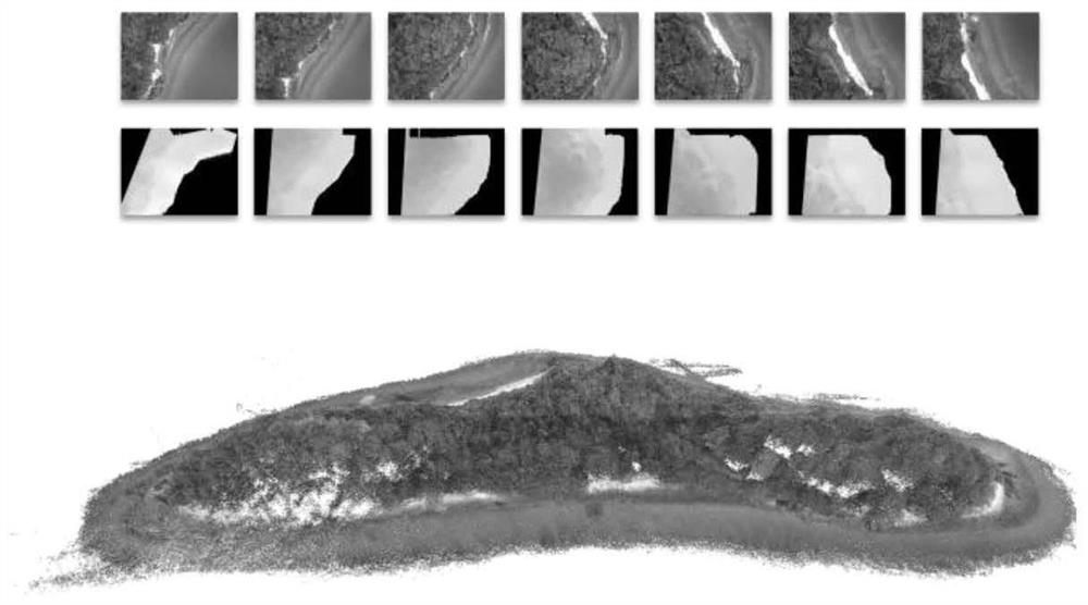
[0139] A three-dimensional point cloud generation unit: used to densify two consecutive frames of original images using the optimal pose of the original image to obtain a depth map; filter the depth map by using a consistency check to obtain a three-dimensional point cloud;

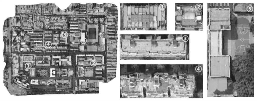
[0140] Model generation unit: used to generate DOM models, DEM models and DSM models using 3D point clouds, and perform multi-band fusion on DOM models, DEM models and DSM models to obtain global DEM models, global DOM models and global DSM models;

[0141] A map generation unit: u...


PUM


Abstract

The invention provides an aerial survey method and system based on real-time dense three-dimensional point cloud of an unmanned aerial vehicle and DSM, and the method comprises the steps: obtaining anoriginal image photographed by a camera in a flight process of the unmanned aerial vehicle, and estimating the camera pose of the original image through the SLAM technology; optimizing the camera pose to obtain an optimal pose; densifying two continuous frames of original images by using the optimal pose to obtain a depth map; filtering the depth map to obtain a three-dimensional point cloud; generating a DOM model, a DEM model and a DSM model by using the three-dimensional point cloud; performing multi-band fusion on the DOM model, the DEM model and the DSM model to obtain a global DEM model, a global DOM model and a global DSM model; and generating a flight map according to the global DSM model; according to the method, the dense three-dimensional point cloud, the digital orthographic image map and the digital earth surface model can be quickly generated from the aerial images of the unmanned aerial vehicle, so that the flight map is generated while the unmanned aerial vehicle flies.

Description

technical field [0001] The invention belongs to the technical fields of computer image processing, computer vision and remote sensing surveying and mapping, and specifically relates to an aerial survey method and system based on real-time dense three-dimensional point cloud and DSM of unmanned aerial vehicles. Background technique [0002] Most of the traditional aerial survey methods are based on the reconstruction of SfM technology, which cannot realize the map while flying. This is because in the process of generating a 3D model based on SfM (Structure from Motion), all images need to be prepared in advance, and computer computing power is highly required. This method can generate camera poses and 3D point clouds for taking photos from many pictures, and use 3D point clouds for fusion, and finally generate dense 3D point clouds, digital orthophoto maps (DOM) and digital surface models (DSM). But the existing technology is generally slower, such as patent CN108765298A. ...

Claims


Application Information

Patent Timeline
Patent Type & Authority Applications(China)
IPC IPC(8): G06K9/46G06K9/00G06K9/62G06T3/40G06T5/00G06T7/80G06T17/05G06F17/16
CPCG06T7/85G06T5/006G06T17/05G06T3/4023G06F17/16G06T2207/10028G06V20/13G06V10/462G06F18/22
Inventor 赵勇
Owner 西安视野慧图智能科技有限公司
Why Eureka
Try Eureka