
Overlay precision detection method and semiconductor structure

A technology of overlay accuracy and detection method, which is applied in the direction of semiconductor devices, semiconductor/solid-state device testing/measurement, electric solid-state devices, etc. It can solve the problem of collapse, inability to effectively detect overlay accuracy, and inability to cover grid lines and channel holes Engraving accuracy detection and other issues

Active Publication Date: 2021-03-02
YANGTZE MEMORY TECH CO LTD
View PDF7 Cites 2 Cited by
  • Summary
  • Abstract
  • Description
  • Claims
  • Application Information

AI Technical Summary

Problems solved by technology

[0004] However, in the 3D-NAND memory manufacturing process, after the step structure is formed, if a gate line mark (gate line mark) is directly formed on the stack structure, that is, an overlay accuracy detection pattern, after removing the sacrificial layer in the stack structure, the gate The area around the line mark is at risk of peeling and cannot be effectively checked for overlay accuracy
Therefore, the existing method can only indirectly judge the gate line and channel by combining the overlay accuracy of the gate line and the dummy channel hole (dummy channel hole) with the overlay accuracy of the dummy channel hole and the upper channel hole (upper channel hole). The overlay accuracy of the hole cannot be directly detected by the grid line mark and the channel hole mark

Method used


Image

  • Overlay precision detection method and semiconductor structure
  • Overlay precision detection method and semiconductor structure
  • Overlay precision detection method and semiconductor structure

Examples


Embodiment Construction

[0037] In order to make the above objects, features and advantages of the present invention more comprehensible, specific implementations of the present invention will be described in detail below in conjunction with the accompanying drawings.

[0038] In the following description, a lot of specific details are set forth in order to fully understand the present invention, but the present invention can also be implemented in other ways different from those described here, and those skilled in the art can do it without departing from the meaning of the present invention. By analogy, the present invention is therefore not limited to the specific examples disclosed below.

[0039] In the semiconductor manufacturing process, the lithography process is an important process. A semiconductor product includes multi-layer functional film layers, and a multi-layer lithography process is required to complete the entire product manufacturing process. For example, the first layer of semicon...


PUM

PropertyMeasurementUnit
thicknessaaaaaaaaaa

Abstract

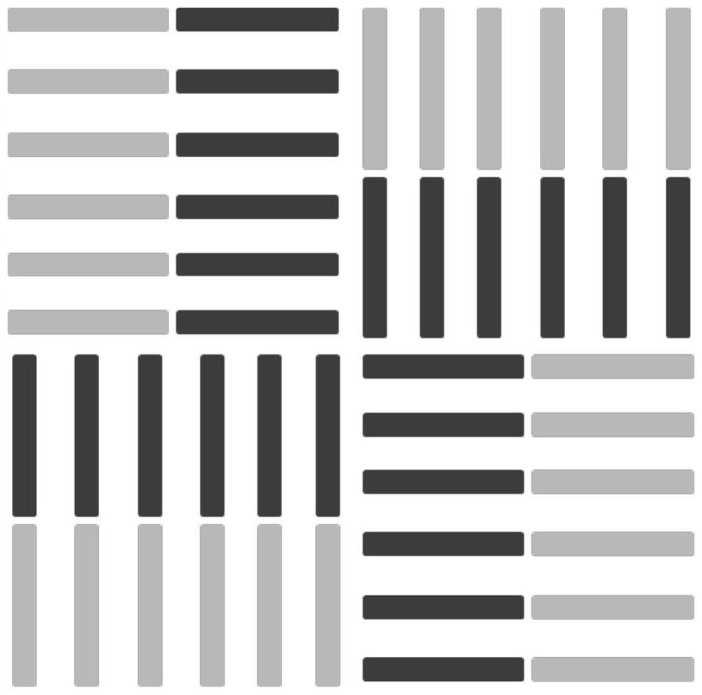
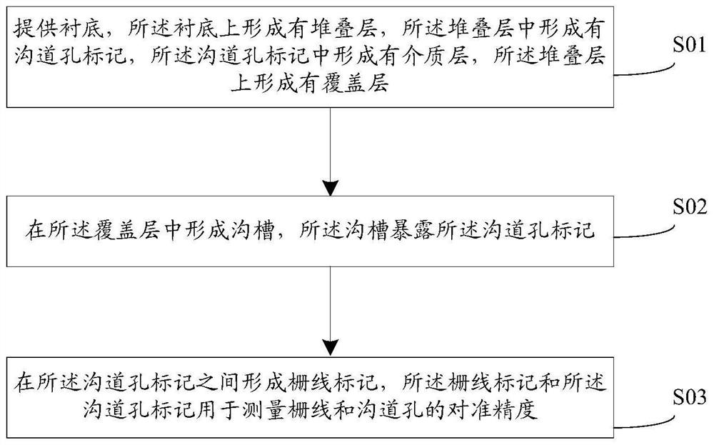
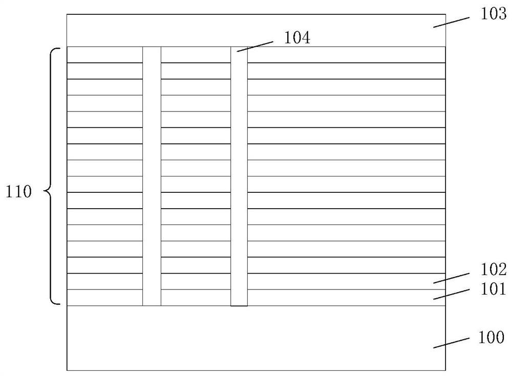
The invention provides an overlay precision detection method and a semiconductor structure. The overlay precision detection method comprises the steps of: providing a substrate, forming a stacking layer on the substrate, forming a channel hole mark in the stacking layer, forming a dielectric layer in the channel hole mark, and forming a covering layer on the stacking layer; forming a groove in thecovering layer, wherein the groove exposes the channel hole mark; and forming grid line marks between the channel hole marks, wherein the grid line marks and the channel hole marks are used for detecting the overlay precision of the grid lines and the channel holes. Thus, the grid line marks are formed among the channel hole marks, and the dielectric layer is formed in the channel hole marks andcan support the stacked layer, so that the risk of collapse of the area around the grid line marks after the sacrificial layer in the stacked structure is removed is avoided, and the reliability of the stacked structure is improved. Therefore, overlay precision detection of the grid lines and the channel holes can be directly realized through the grid line marks and the channel hole marks.

Description

technical field [0001] The invention relates to the technical field of semiconductors, in particular to an overlay precision detection method and a semiconductor structure. Background technique [0002] Photolithography is an important step in the manufacturing process in the semiconductor field. Photolithography is the process of transferring the pattern on the mask plate to the target substrate through steps such as alignment, exposure, and development. A semiconductor product consists of multi-layer functional film layers, and multi-layer photolithography is required to complete the entire product manufacturing process. The position alignment of the current functional film layer and the previous layer of functional film layers is particularly important. Overlay testing is the key to semiconductor manufacturing. A basic process in the photolithography process, the overlay accuracy reflects the degree of alignment between different functional film layers. [0003] The ove...

Claims


Application Information

Patent Timeline
Patent Type & Authority Applications(China)
IPC IPC(8): H01L21/66H01L27/1157H01L27/11582G03F7/20H10B43/27H10B43/35
CPCH01L22/12H01L22/30G03F7/70633G03F7/70616G03F7/70683G03F7/7085H10B43/35H10B43/27
Inventor 卢绍祥陆聪
Owner YANGTZE MEMORY TECH CO LTD
Learn More