
Steel plate heat treatment machining equipment capable of achieving different cooling modes

A cooling method and processing equipment technology, applied in heat treatment equipment, heat treatment furnaces, manufacturing tools, etc., can solve the problems of reducing the heating efficiency of steel plates, the position cannot be fixed well, and the effect of heat treatment processing of steel plates, etc., so as to improve the practicality Sexuality, improved effect and efficiency, and convenient heating effect

Inactive Publication Date: 2021-03-05
武穴市明晖重工有限公司
View PDF0 Cites 0 Cited by
  • Summary
  • Abstract
  • Description
  • Claims
  • Application Information

AI Technical Summary

Problems solved by technology

A remarkable progress is that from 1901 to 1925, the rotary furnace was used for gas carburizing in industrial production; the dew point potentiometer appeared in the 1930s, which made the carbon potential of the atmosphere in the furnace controllable, and later developed the carbon dioxide infrared instrument. , oxygen probe and other methods to further control the carbon potential of the furnace atmosphere; in the 1960s, the heat treatment technology used the plasma field to develop the ion nitriding and carburizing process; the application of laser and electron beam technology made the metal obtain new Surface heat treatment and chemical heat treatment methods; when the existing steel plate heat treatment processing device is heat-treating the steel plate, the position of the steel plate cannot be fixed well, thereby affecting the effect of the steel plate heat treatment processing, and the existing steel plate heat treatment processing device is not very good for the steel plate The processing efficiency of the heat treatment is low. At the same time, when it is necessary to heat different positions of the steel plate, the steel plate needs to be moved, which reduces the efficiency of the steel plate heating.

Method used


Image

  • Steel plate heat treatment machining equipment capable of achieving different cooling modes

Examples


Embodiment Construction

[0011] The following will clearly and completely describe the technical solutions in the embodiments of the present invention with reference to the accompanying drawings in the embodiments of the present invention. Obviously, the described embodiments are only some, not all, embodiments of the present invention. Based on the embodiments of the present invention, all other embodiments obtained by persons of ordinary skill in the art without making creative efforts belong to the protection scope of the present invention.

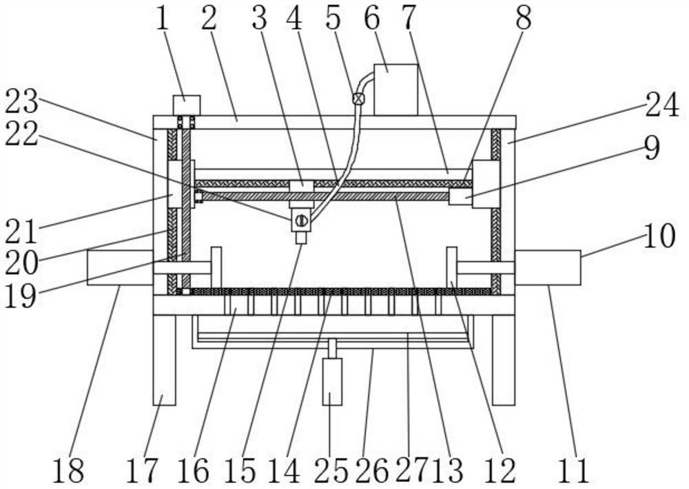
[0012] see figure 1 , in an embodiment of the present invention, a steel plate heat treatment processing equipment that can realize different cooling methods, including a first motor 1, a mounting plate 2, a first slider 3, an air duct 4, a fuel tank 6, a horizontal plate 7, a first Slide rail 8, second motor 9, first screw rod 13, heat insulating material layer 14, nozzle 15, base 16, support leg 17, second screw rod 19, second slide rail 20, second slider 21...


PUM


Abstract

The invention discloses steel plate heat treatment machining equipment capable of achieving different cooling modes. The steel plate heat treatment machining equipment is provided with a first fixingdevice and a second fixing device for extruding two corresponding sides of a steel plate, so that the steel plate is fixed to the top of a base. A guide valve is opened, fuel in a fuel tank enters a spray head through an air guide pipe and then is further sprayed out of a nozzle to be combusted to heat the steel plate, a first motor rotates to drive a second screw to rotate, movement of second sliding blocks on second sliding rails is achieved, and therefore the height of the nozzle is adjusted. Steel plates with different thicknesses can be heated conveniently, a second motor rotates to drivea first screw rod to rotate, then a first sliding block moves on a first sliding rail, the purpose of heating the different positions of the steel plates is achieved, the steel plates do not need tobe moved, and the heating effect and efficiency are improved.

Description

technical field [0001] The invention relates to the technical field of heat treatment processing, in particular to a steel plate heat treatment processing equipment capable of realizing different cooling methods. Background technique [0002] Since the 20th century, the development of metal physics and the transplantation and application of other new technologies have made the metal heat treatment process more developed. A remarkable progress is that from 1901 to 1925, the rotary furnace was used for gas carburizing in industrial production; the dew point potentiometer appeared in the 1930s, which made the carbon potential of the atmosphere in the furnace controllable, and later developed the carbon dioxide infrared instrument. , oxygen probe and other methods to further control the carbon potential of the furnace atmosphere; in the 1960s, the heat treatment technology used the plasma field to develop the ion nitriding and carburizing process; the application of laser and el...

Claims


Application Information

Patent Timeline
IPC IPC(8): C21D9/00C21D1/52
CPCC21D1/52C21D9/0081
Inventor 彭静戴宏强
Owner 武穴市明晖重工有限公司
Learn More