Rotary needleless spinning device

A rotary, needle-spinning technology, used in textiles and papermaking, filament/thread forming, fiber processing, etc., can solve the problems of easy change of physical or chemical properties of the solution, unstable spinning, etc., and achieve the physical or chemical properties of the solution. Stable, guaranteed physical or chemical properties, guaranteed uniformity of effect

Pending Publication Date: 2021-03-05
SHANDONG HUANGHE DELTA INST OF TEXTILE SCI & TECH RES INST
View PDF11 Cites 1 Cited by
  • Summary
  • Abstract
  • Description
  • Claims
  • Application Information

AI Technical Summary

Problems solved by technology

[0005] Aiming at the problems in the above-mentioned prior art that the spinning electrode solution is exposed to the air too much, the physical or chemical properties of the solution are easily changed, and the spinning is unstable, the present invention provides a rotary needleless spinning device. The electrode cover plate greatly reduces the exposed area of ​​the solution, and the space outside the hollow disc is also covered with a cover plate to minimize the direct contact between the solution and the air

Method used


Image

  • Rotary needleless spinning device
  • Rotary needleless spinning device
  • Rotary needleless spinning device

Examples


Embodiment 1

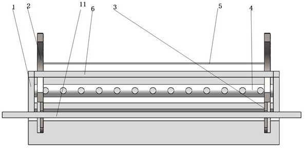
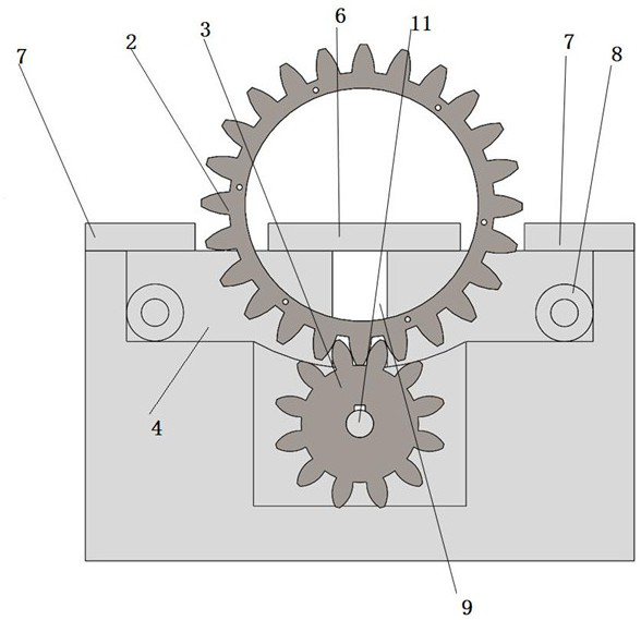
[0029] A rotary needleless spinning device, such as Figure 1-3 As shown, the device body 1 is included, the device body is provided with a hollow disc 2, a rotating gear 3 and a solution tank 4, the hollow disc is provided with an electrode wire 5, and the rotating gear can drive the hollow disc to rotate , so as to drive the electrode wire on the hollow disc to rotate; the solution tank is arranged below the hollow disc, and when the hollow disc rotates, a part at the lower part is always in the solution tank, so that the hollow The electrode wire on the disc can walk through the solution in the solution tank, and take part of the liquid when it rotates out of the liquid surface.

[0030] The device body is also provided with an electrode inner cover plate 6 and an electrode outer cover plate 7, and the electrode inner cover plate covers the inner side of the hollow disk and the cavity above the apex of the rotating gear; the overall height of the electrode outer cover plate...

Embodiment 2

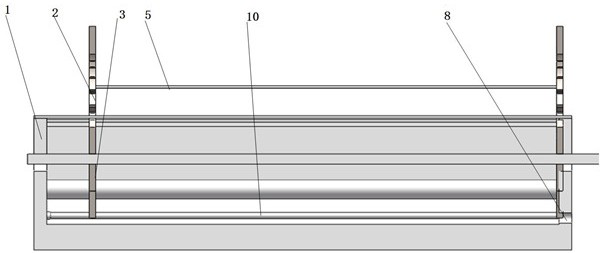
[0039] A rotary needleless spinning device, such as Figure 4 As shown, the device body 1 is included, the device body is provided with a hollow disc 2, a rotating gear 3 and a solution tank 4, the hollow disc is provided with an electrode wire 5, and the rotating gear can drive the hollow disc to rotate , so as to drive the electrode wire on the hollow disc to rotate; the solution tank is arranged below the hollow disc, and when the hollow disc rotates, a part at the lower part is always in the solution tank, so that the hollow The electrode wire on the disc can walk through the solution in the solution tank, and take part of the liquid when it rotates out of the liquid surface.

[0040] The device body is also provided with an electrode inner cover plate 6 and an electrode outer cover plate 7, and the electrode inner cover plate covers the inner side of the hollow disk and the cavity above the apex of the rotating gear; the overall height of the electrode outer cover plate i...


PUM


Abstract

The invention belongs to the technical field of electrostatic spinning, and particularly relates to a rotary needleless spinning device which comprises a device body, wherein a hollow disc, a rotatinggear and a solution tank are arranged on the device body, an electrode wire is arranged on the hollow disc, the rotating gear can drive the hollow disc to rotate so as to drive the electrode wire onthe hollow disc to rotate, the solution tank is arranged below the hollow disc, and when the hollow disc rotates, one part of the lower part of the hollow disc is always positioned in the solution tank, so that the electrode wire on the hollow disc can pass through a solution in the solution tank, and part of the liquid is brought out when the electrode wire rotates out of a liquid level. According to the spinning device, the rotary electrode is adopted, manufacturing is convenient, the spinning field intensity of the electrode wire is uniform, and the stability of the physical or chemical property of the spinning solution in the spinning process can be guaranteed.

Description

technical field [0001] The invention belongs to the technical field of electrostatic spinning, and in particular relates to a rotary needleless spinning device. Background technique [0002] Electrospinning is a special form of electrostatic atomization of polymer fluids. At this time, the substances split by the atomization are not tiny droplets, but tiny jets of polymers, which can run for a long distance and finally solidify into fibers. [0003] Electrospinning technology is a special fiber manufacturing process. The polymer solution or melt is jet-spun in a strong electric field. Under the action of the electric field, the droplet at the needle will change from a spherical shape to a conical shape—that is, a Taylor cone. Fiber filaments are extended from the tip of the cone, which can produce polymer filaments with nanometer diameters. [0004] In recent years, the electrospinning process has received more and more attention in the industry. Because of its extremely fi...

Claims


Application Information

Patent Timeline
Patent Type & Authority Applications(China)
IPC IPC(8): D01D5/00
CPCD01D5/0069
Inventor 张雷健房宽峻牛海涛刘成禄赵书孝李涛申春苗刘珍珍朱子玉刘曰兴
Owner SHANDONG HUANGHE DELTA INST OF TEXTILE SCI & TECH RES INST
Why Eureka
Try Eureka