Eureka AIR delivers breakthrough ideas for toughest innovation challenges, trusted by R&D personnel around the world.

Reactor core melt capturing apparatus capable of realizing reinforced cooling through split charging

A core melt and reactor technology, applied in the field of nuclear safety control, can solve the problems of large layout space, many links, and long migration path of melt

Active Publication Date: 2018-05-18
CHINA NUCLEAR POWER ENG CO LTD
View PDF17 Cites 3 Cited by
  • Summary
  • Abstract
  • Description
  • Claims
  • Application Information

AI Technical Summary

Problems solved by technology

[0007] However, the above-mentioned EVR technical solutions have the following problems: regardless of the deep-water pool or the shallow-water pool, there is a risk of steam explosion; the simple water injection and submersion on the top of the molten material have poor cooling effects on the molten material; The collector requires a larger expansion chamber, and the melt migration path is longer and has more links; the problem of requiring a larger layout space exists in the core catcher scheme of ESBWR and EU-APR1400, while the relatively compact layout The core catcher of VVER1000 needs at least 10 months for the final cooling of the melt after the melt retention is achieved

Method used


Image

  • Reactor core melt capturing apparatus capable of realizing reinforced cooling through split charging
  • Reactor core melt capturing apparatus capable of realizing reinforced cooling through split charging
  • Reactor core melt capturing apparatus capable of realizing reinforced cooling through split charging

Examples


Embodiment Construction

[0064] The specific implementation manners of the present invention will be further described below in conjunction with the accompanying drawings.

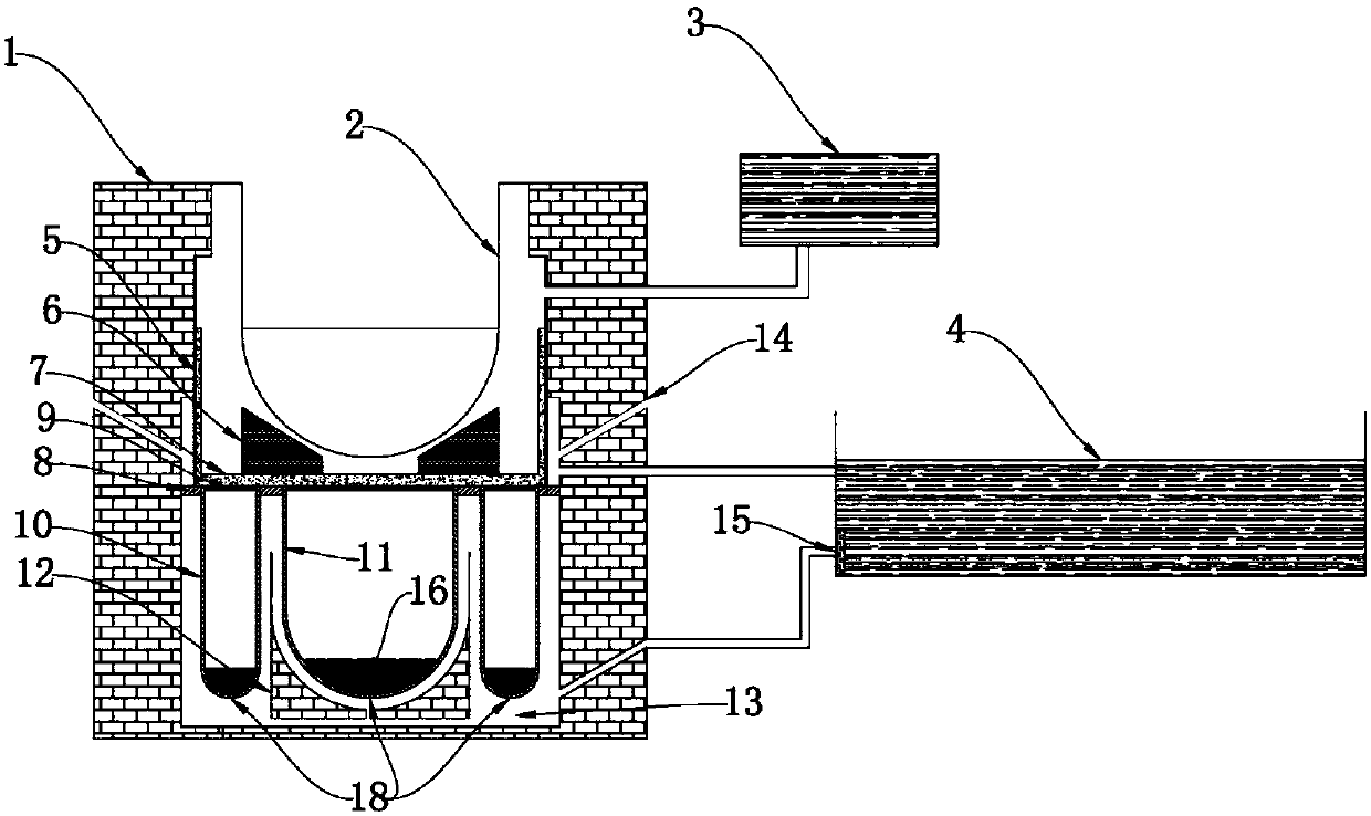
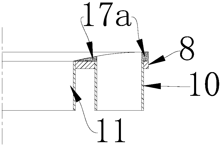
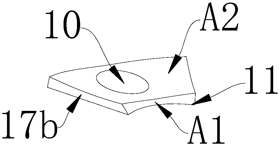
[0065] The composition of the reactor core melt collection device of the exemplary sub-package enhanced cooling of the present invention and a part of its structure are as follows: Figure 1-4As shown, the trapping device includes a reactor pit 1, a reactor pressure vessel (RPV) 2, a stagnant water tank 3, a cooling water tank 4, a smelt retention vessel 5 (including a bottom plate 8), a shock absorber 6 (or grid plate 6) , sacrificial material 7, melting plug 9, auxiliary crucible 10, main crucible 11, flow guiding device 12, cooling space 13, steam discharge port 14, filter 15, filler 16, melt guiding device 17, inner bottom of the crucible Head 18, protective layer 19 (can be protective layer 19a or protective layer 19b), high melting point metal 20 (can be high melting point metal or alloy 20a or high melting point metal or al...


PUM


Abstract

The invention relates to a reactor core melt capturing apparatus capable of realizing reinforced cooling through split charging, belonging to the technical field of nuclear safety control. The reactorcore melt capturing apparatus comprises a reactor pit, a reactor pressure vessel, a melt retention container, crucibles, a retention water tank, a cooling water tank and connecting pipelines, whereinthe melt retention container with an opened top is located in the reactor pit; the lower part and the bottom of the reactor pressure vessel are located in the melt retention container; space, locatedbelow the melt retention container, in the reaction pit forms cooling space; the crucibles are arranged in the reaction pit and located below the base plate of the melt retention container; the retention water tank is located out of the reaction pit and connected with the reaction pit via one connecting pipeline; and the cooling water tank is located out of the reaction pit and connected with thecooling space via another connecting pipeline. The reactor core melt capturing apparatus provided by the invention can cope with serious accidents in a nuclear power station by employing compactly arranged core catchers with high cooling efficiency and realizing effective capturing and accommodating of core melts through temporary retention and reinforced cooling via split charging.

Description

technical field [0001] The invention belongs to the technical field of nuclear safety control, and relates to a reactor core melt collection device for subpackage enhanced cooling. Background technique [0002] Severe accidents in nuclear power plants began with large-scale melting of reactor fuel assemblies. At this time, the fuel cladding, the first barrier of the defense-in-depth system, has failed. If the reactor cannot be cooled in time, the related reactor internals will also be melted and form Core melt, falling into the reactor pressure vessel (RPV) lower head. In the case of insufficient external cooling of the RPV lower head, the RPV lower head will be melted, that is, the pressure boundary of the second barrier and the primary circuit is broken, and the core melt enters the containment vessel. After the pressure vessel melts through, the molten material is directly sprayed onto the raft foundation of the containment to interact with the structural concrete (MCCI)...

Claims


Application Information

Patent Timeline
Patent Type & Authority Applications(China)
IPC IPC(8): G21C9/016
CPCG21C9/016Y02E30/30
Inventor 元一单马卫民李炜郭强张丽朱晨王洪亮邹文重于明锐韩旭冯雨亓振锋刘卓
Owner CHINA NUCLEAR POWER ENG CO LTD
Why Eureka
Eureka Blog
Learn More