Combustor fire grate, combustor and water heater

A burner and fire row technology, applied in the field of burners, can solve the problems of unstable combustion flame smoke, combustion resonance and fire off, and high carbon monoxide emissions, so as to improve comfort and safety, improve stability, and reduce emissions Effect

Inactive Publication Date: 2021-03-05
WUHU MIDEA KITCHEN & BATH APPLIANCES MFG CO LTD +1
View PDF0 Cites 2 Cited by
  • Summary
  • Abstract
  • Description
  • Claims
  • Application Information

AI Technical Summary

Problems solved by technology

[0003] Existing burners for gas water heaters are mostly atmospheric burners. The fire holes of atmospheric burners have three structures: inner V hole, outer V hole and plane hole. Although the inner V hole structure is conducive to combustion noise, the emission is relatively low. The outer V hole structure is good for discharge, but it is easy to cause combustion resonance and fire off. The higher flame height of the outer V hole structure will cause adverse consequences such as ablation of the heat exchanger, reducing heat loss. The service life of the exchanger, the performance of the planar structure is between the two
During the operation of the existing burner, there will be safety hazards such as deflagration due to poor fire transmission, and the problem of high carbon monoxide emissions in the flue gas due to unstable combustion flame

Method used


Image

  • Combustor fire grate, combustor and water heater
  • Combustor fire grate, combustor and water heater
  • Combustor fire grate, combustor and water heater

Examples


Embodiment 1

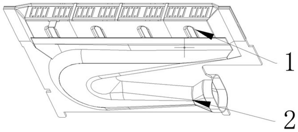
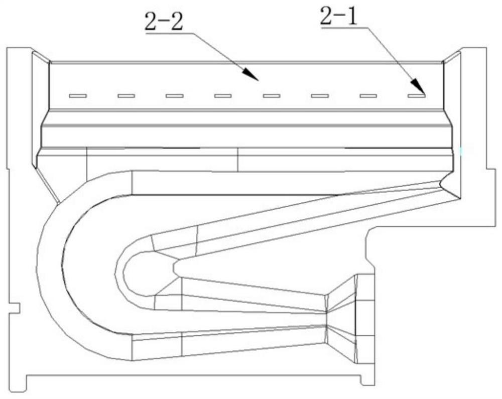
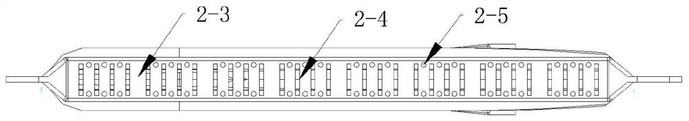
[0061]A burner row, such asFigure 1-4As shown, including the premix cavity 2 and the flame flame 1, the premix chamber 2 includes a cavity and an out-of-end end, and the end surface of the fire end is provided with a plurality of strip of the long flaps 2-4 that are parallel to each other, and a plurality of circles are also provided Fire holes 2-5, two circular flakes 2-5 are a circular flake group, and the long strip flakes 2-4 and the circular flake set are arranged in the longitudinal direction of the fire surface 2-3. The side 2-2 of the fire end is opened with a plurality of parallel arranged side flakes 2-1 for discharging part of the gas. The two stable flakes 1 are fixed to both sides of the hot end of the premixing cavity. The area of ​​the circular flakes 2-5 is smaller than the area of ​​the side flakes 2-1.

[0062]The long strip flavor 2-4 almost through the width direction of the fire surface 2-3, and the two circular flakes of the circular flake group are formed at both...

Embodiment 2

[0067]In this first embodiment, the improvement in the basis of Example 1, the first reinforcing rib between the side surface of the flame piece and the outlet end, and the first reinforcing rib is fitted to the side surface of the fire end. The circular fire hole as the sub-finger hole is replaced with a square hole, and the square hole is one, and is in the central region of the fire surface unit between the adjacent two long flaps.

Embodiment 3

[0069]In this first embodiment, an improvement made on the basis of Example 1, replaced with an elliptical hole as an elliptical aperture as a circular fire hole of the sub-finifier, and the resilience is arranged between the adjacent two long flakes. One long strip flame in Example 1 was in a multi-segment form in this embodiment.


PUM


Abstract

The invention relates to the technical field of combustors, in particular to a combustor fire grate, a combustor and a water heater. The combustor fire grate comprises a premixing cavity, wherein thefire outlet end of the premixing cavity is provided with a fire outlet face, the fire outlet face is provided with fire outlet holes, the fire outlet holes comprise a plurality of main fire holes anda plurality of auxiliary fire holes, all the main fire holes are arranged in parallel, and the auxiliary fire holes are formed between every two adjacent main fire holes among part or all of the mainfire holes. According to the combustor, the auxiliary fire holes are formed between every two adjacent main fire holes in the fire outlet face 2-3 of the unique premixing cavity, so that the main fireholes and the auxiliary fire holes are basically formed alternately, good fire transferring and flame stabilizing performance is achieved, combustion noise is lowered, the combustion discharge amountis reduced, better performance experience is brought to consumers, the using comfort of the water heater is improved, moreover, the emission of carbon monoxide can be effectively reduced, and the usesafety of the water heater is improved.

Description

Technical field[0001]The present invention relates to the field of burner, in particular, to burner, burner, and hot water equipment.Background technique[0002]With energy saving and emission reduction, the implementation of coal-to-gas policies, gas water heaters have become long-term development, which has become an indispensable product in consumers. With the improvement of living standards, consumers are getting higher and higher in quality requirements for gas water heaters. Consumers have put forward higher requirements for the comfort and safety of gas water heaters.[0003]The existing gas water heater combustor is mostly an air burner. The fire hole of the air burner has three structures in the inner V hole, the outer V hole, and the plane holes. Although the inner V-hole structure is conducive to the combustion noise but the discharge is relatively Poor, and very easy to have a tempering phenomenon; the outer V pore structure is conducive to emissions, but it is easy to cause...

Claims


Application Information

Patent Timeline
Patent Type & Authority Applications(China)
IPC IPC(8): F23D14/04F23D14/26F23D14/46F23D14/58F23D14/62
CPCF23D14/045F23D14/26F23D14/46F23D14/58F23D14/62F23D2203/007
Inventor 王晓宁梁国荣
Owner WUHU MIDEA KITCHEN & BATH APPLIANCES MFG CO LTD
Why Eureka
Try Eureka