Overmodulation-based flux weakening control method and device for permanent magnet synchronous motor

A permanent magnet synchronous motor and field weakening control technology, applied in the field of servo drive, can solve the problem of low utilization rate of DC bus voltage and so on

Inactive Publication Date: 2021-03-05
清能德创电气技术(北京)有限公司 +1
View PDF5 Cites 1 Cited by
  • Summary
  • Abstract
  • Description
  • Claims
  • Application Information

AI Technical Summary

Problems solved by technology

Solve the problem of low utilization rate of the DC bus voltage by the existing field-weakening control by over-modulation algorithm control combined with field-weakening control, and keep the phase voltage of the motor at the thresh...

Method used


Image

  • Overmodulation-based flux weakening control method and device for permanent magnet synchronous motor
  • Overmodulation-based flux weakening control method and device for permanent magnet synchronous motor
  • Overmodulation-based flux weakening control method and device for permanent magnet synchronous motor

Examples


Embodiment 1

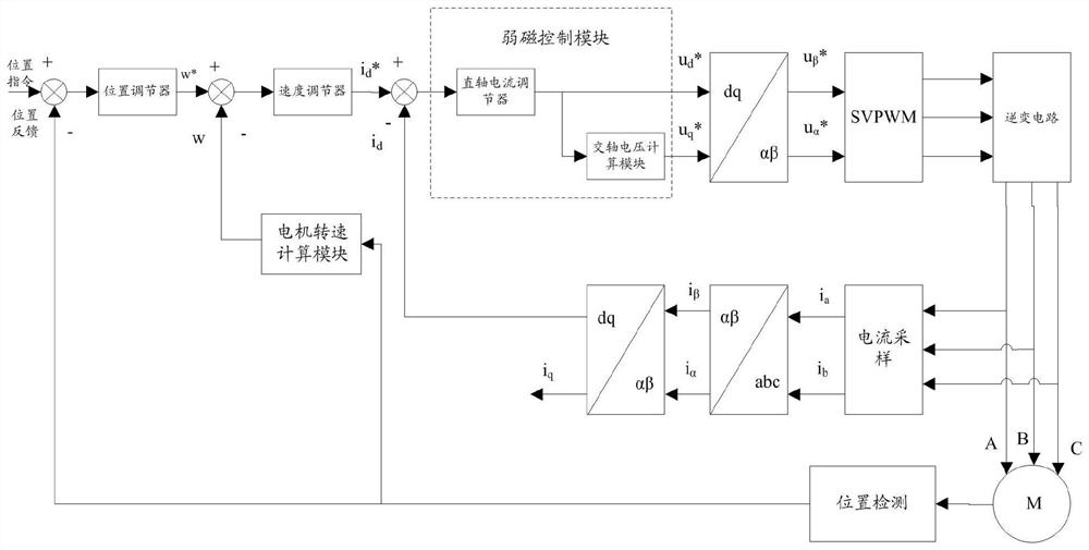
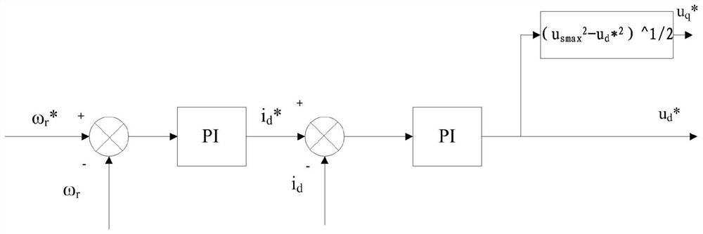
[0065] Pure field weakening control cannot make the permanent magnet synchronous motor utilize the DC bus voltage to the greatest extent. In order to enable the permanent magnet synchronous motor to utilize the DC bus voltage to the greatest extent, this embodiment provides a field weakening control device for the permanent magnet synchronous motor based on overmodulation. Such as figure 1 As shown, the permanent magnet synchronous motor field weakening control device based on overmodulation includes: a position regulator, a speed regulator, a field weakening control module, a first coordinate converter, a second coordinate converter, a third coordinate converter, a space vector Pulse width modulator, inverter circuit, current sampling module, position detection module, motor speed calculation module.

[0066] In the control of permanent magnet synchronous motors, in order to obtain the control characteristics similar to DC motors, a coordinate system is established on the ro...

Embodiment 2

[0085] This embodiment is used to provide an overmodulation-based permanent magnet synchronous motor field weakening control method, using the overmodulation based permanent magnet synchronous motor field weakening control device described in Embodiment 1 to work, as Figure 5 As shown, the overmodulation-based permanent magnet synchronous motor field weakening control method includes the following steps:

[0086] Step 1: According to the DC bus voltage U dc Get the field weakening control threshold voltage u s max ;

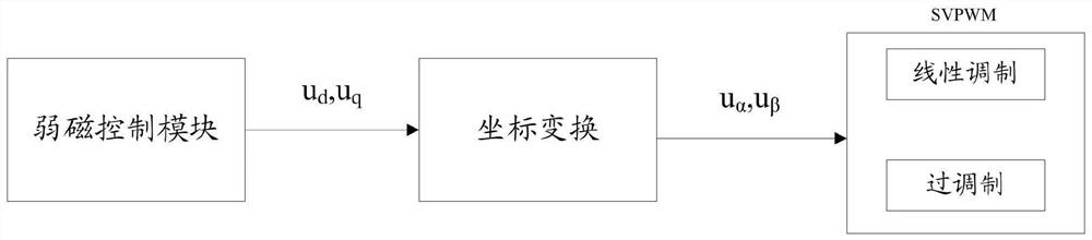
[0087] The threshold voltage of the field weakening control is u s max is 0.577 times the DC bus voltage Udc ,because Figure 4 The value of the radius of the small and medium circles is also 0.577 times the amplitude of the DC bus voltage, so the permanent magnet synchronous motor will also perform overmodulation control when it enters the field weakening control. The field-weakening control and the over-modulation control the permanent magnet synchronous m...


PUM


Abstract

The invention relates to a permanent magnet synchronous motor flux weakening control device and method based on overmodulation. The method comprises the steps: acquiring the flux weakening control threshold voltage usmax; obtaining a stator end voltage vector amplitude us of the permanent magnet synchronous motor in real time; comparing the stator end voltage vector amplitude us with the flux-weakening control threshold voltage usmax, if the stator end voltage vector amplitude us is smaller than the flux-weakening control threshold voltage usmax, controlling the permanent magnet synchronous motor by an id = 0 control algorithm, and controlling the permanent magnet synchronous motor inverter by an existing SVPWM linear modulation algorithm; if the stator end voltage vector amplitude us is equal to the flux-weakening control threshold voltage usmax, continuing to increase the rotating speed or load of the motor, controlling the permanent magnet synchronous motor by using a flux-weakeningcontrol algorithm, and controlling the permanent magnet synchronous motor inverter by using an SVPWM over-modulation algorithm. Compared with the prior art, the dynamic performance of the flux-weakening control process is good.

Description

technical field [0001] The invention belongs to the technical field of servo drive, and in particular relates to a field weakening control method and device for a permanent magnet synchronous motor based on overmodulation. Background technique [0002] In servo control applications, limited by the input voltage of the driver, when the permanent magnet synchronous motor (PMSM) needs to run above the base speed, it is necessary to perform field-weakening control on the motor. [0003] The traditional negative id compensation field weakening algorithm is based on the adjustment of the AC and DC axis current id and iq, and plans the motor stator current trajectory on the id-iq coordinate plane. This method needs to design two current loops of direct axis and quadrature axis at the same time. In the adjustment process, a pure integral controller or a proportional integral controller is usually used to purely control the difference between the output voltage vector amplitude and t...

Claims


Application Information

Patent Timeline
IPC IPC(8): H02P21/00H02P25/022
CPCH02P21/0089H02P21/0003H02P21/0021H02P25/022H02P2207/05
Inventor 赵茵茵刘波汤小平
Owner 清能德创电气技术(北京)有限公司
Why Eureka
Try Eureka