Mixing and stirring equipment for coating production

A technology of mixing and stirring equipment, applied in mixers, mixer accessories, shaking/oscillating/vibrating mixers, etc., can solve the problems of lack of pretreatment means, quality of finished paint products, and obstruction of stone powder mixing and stirring.

Inactive Publication Date: 2021-03-09
安徽云至信电子商务有限公司
View PDF0 Cites 7 Cited by
  • Summary
  • Abstract
  • Description
  • Claims
  • Application Information

AI Technical Summary

Problems solved by technology

[0012] Most of the powder coatings are made of a variety of powdery stones and additives mixed in a certain proportion; most of the raw materials for making this type are stone powder, which are usually piled up and stored. Due to the high humidity of the surrounding environment or some raw materials themselves There is a certain degree of water absorption, and it will be agglomerated by the moisture in the air during storage, so that in the subsequent preparation, the agglomerated stone powder will become an obstacle to mixing;
[0013] However, the existing mixing equipment lacks effective pretreatment means for this kind of raw materials mixed with agglomerated stone powder, and it is easy for stone powder blocks to directly participate in the stirring, making the quality of the finished coating lower or even unqualified; in addition, the existing equipment There is also room for improvement in the mixing effect of stone powder

Method used


Image

  • Mixing and stirring equipment for coating production
  • Mixing and stirring equipment for coating production
  • Mixing and stirring equipment for coating production

Examples


Embodiment 1

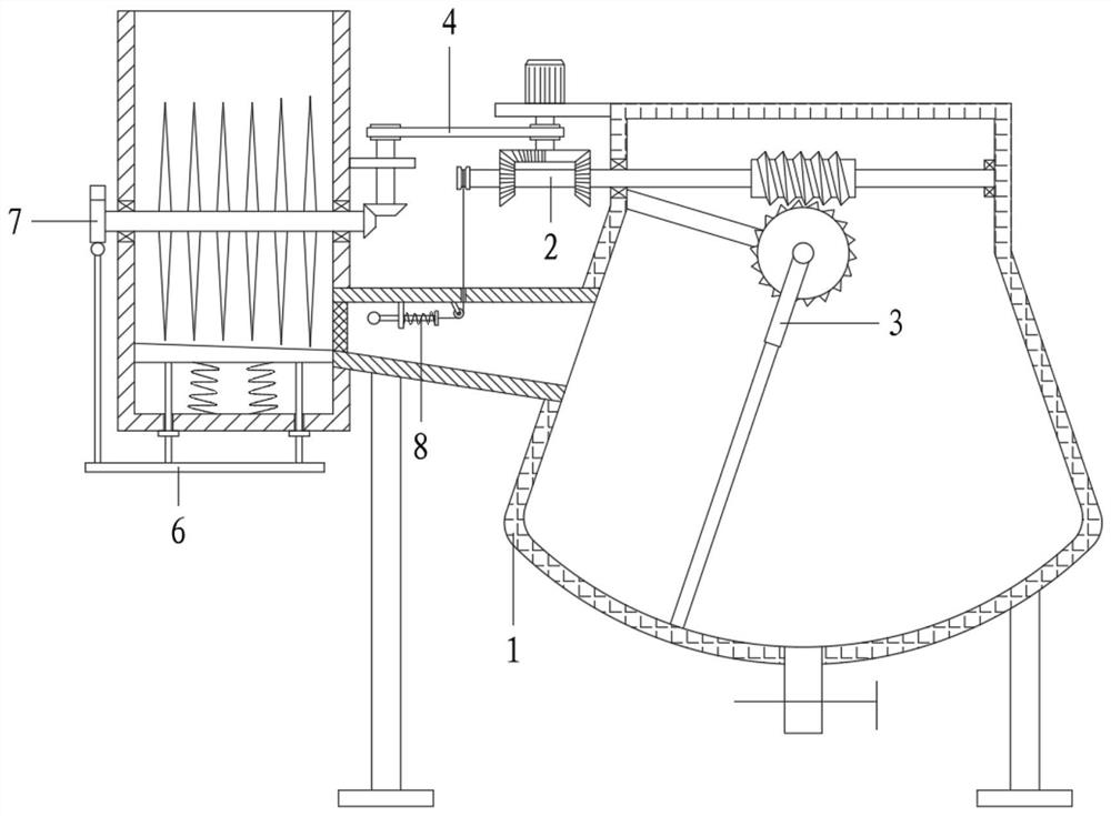
[0065] With reference to the accompanying drawings, a mixing and stirring equipment for paint production includes a tank assembly 1, a driving assembly 2, a stirring assembly 3, a transmission assembly 4 and a crushing assembly 5;

[0066] The tank assembly 1 includes a raw material barrel 101, a feed pipe 102, a stirring tank 103, a material guide plate 104, a screen 105, a paint discharge pipe 106 and a leg 107; the right side of the raw material barrel 101 is connected to the stirring tank 103 through the feeding pipe 102 The upper part; the bottom of the feeding pipe 102 is arranged with a high left and a low right, and a screen 105 is also installed at the left end; a material guide plate 104 is housed in the raw material barrel 101, and the top surface of the material guide plate 104 is processed with a slope that is high on the left and low on the right. The left end of 102 is set corresponding to the right end of the material guide plate 104; the bottom of the stirring ...

Embodiment 2

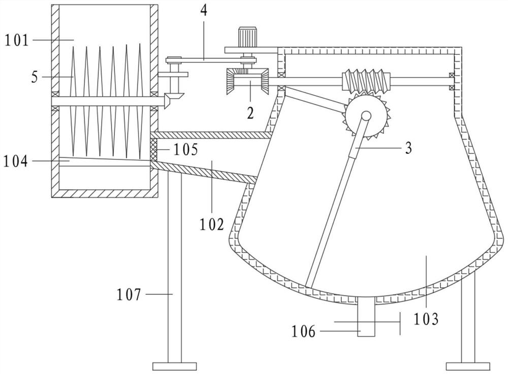
[0069] With reference to the accompanying drawings, a mixing and stirring equipment for paint production includes a tank assembly 1, a driving assembly 2, a stirring assembly 3, a transmission assembly 4 and a crushing assembly 5;

[0070] The tank assembly 1 includes a raw material barrel 101, a feed pipe 102, a stirring tank 103, a material guide plate 104, a screen 105, a paint discharge pipe 106 and a leg 107; the right side of the raw material barrel 101 is connected to the stirring tank 103 through the feeding pipe 102 The upper part; the bottom of the feed pipe 102 is arranged with a high left and a low right, and a screen 105 is also installed at the left end; a material guide plate 104 is fixed inside the raw material barrel 101, and the top surface of the material guide plate 104 is processed with a slope that is high on the left and low on the right. The left end of the pipe 102 is set corresponding to the right end of the material guide plate 104; the bottom of the ...

Embodiment 3

[0086] The difference from Embodiment 2 is that the material guide plate 104 of this embodiment is movable.

[0087] It also includes a pushing assembly 6; the pushing assembly 6 includes a push-pull rod 601, a type of connecting rod 602, a limit block 603 and a type of spring 604;

[0088] The material guide plate 104 is slidably connected in the raw material barrel 101, and a type of spring 604 is connected to the bottom surface of the raw material barrel 101; The bottom is also connected with a push-pull rod 601 ;

[0089] Specifically, under the action of a type of spring 605, the material guide plate 104 always has a tendency to move upward, and is prevented from colliding with the crushing knife 503 by the action of the limit block 603; The stone powder blocks that the knife 503 has fully acted on will accumulate on the material guide plate 104, pull down the push-pull rod 601 and drive the material guide plate 104 to move down a certain distance synchronously, then rel...


PUM


Abstract

The invention relates to the technical field of powder coating preparation, in particular to mixing and stirring equipment for coating production. A servo motor is adopted to drive a motor shaft to rotate, the motor shaft enables a second rotating shaft to rotate under the action of a transmission wheel set and a transmission belt, a first bevel gear at the bottom end of the second rotating shaftalso rotates along with the second rotating shaft, and the second bevel gear is driven to drive a third rotating shaft to rotate, so that a crushing knife crushes stone powder, and caked stone powderis refined again, stone powder is guided by the material guide plate and screened by the screen, so that the stone powder meeting the requirements passes through the material guide plate and falls into the stirring tank after passing through the material guide pipe, and subsequent mixing and stirring are facilitated, an incomplete bevel gear at the bottom end of a motor shaft also rotates synchronously and is in intermittent fit with the first driven bevel gear, so that a second rotating shaft drives a worm to rotate forwards and backwards in a reciprocating manner, the worm drives the worm wheel to rotate in a reciprocating manner, and drives the stirring blades to swing in a reciprocating manner in the stirring tank through the connecting shaft, so that the stone powder raw materials aremixed.

Description

technical field [0001] The invention relates to the technical field of powder coating preparation, and relates to a mixing and stirring equipment for coating production, in particular to a mixing and stirring equipment for coating production with the function of processing stone powder blocks. Background technique [0002] Paint, traditionally called paint in China. The so-called paint is coated on the surface of the object to be protected or decorated, and can form a continuous film firmly attached to the object to be coated, usually based on resin, oil, or emulsion, with or without adding pigments, fillers, adding The corresponding additives are viscous liquids prepared with organic solvents or water. [0003] Coatings belong to organic chemical polymer materials, and the formed coating film belongs to the type of polymer compounds. According to the classification of modern chemical products, coatings belong to fine chemical products. Modern coatings are gradually becom...

Claims


Application Information

Patent Timeline
Patent Type & Authority Applications(China)
IPC IPC(8): B01F13/10B01F11/04B01F15/00B01F31/42
CPCB01F31/42B01F33/831B01F35/181B01F2101/30
Inventor 黄彦子
Owner 安徽云至信电子商务有限公司
Why Eureka
Try Eureka