Ceramic production raw material grinding treatment equipment
A technology for processing equipment and raw materials, which is applied in the field of grinding and processing equipment for ceramic production raw materials, and can solve the problems of automatic mixing of mud, manual mixing of production raw materials, and low grinding efficiency.
- Summary
- Abstract
- Description
- Claims
- Application Information
AI Technical Summary
Problems solved by technology
Method used
Image
Examples
Embodiment 1
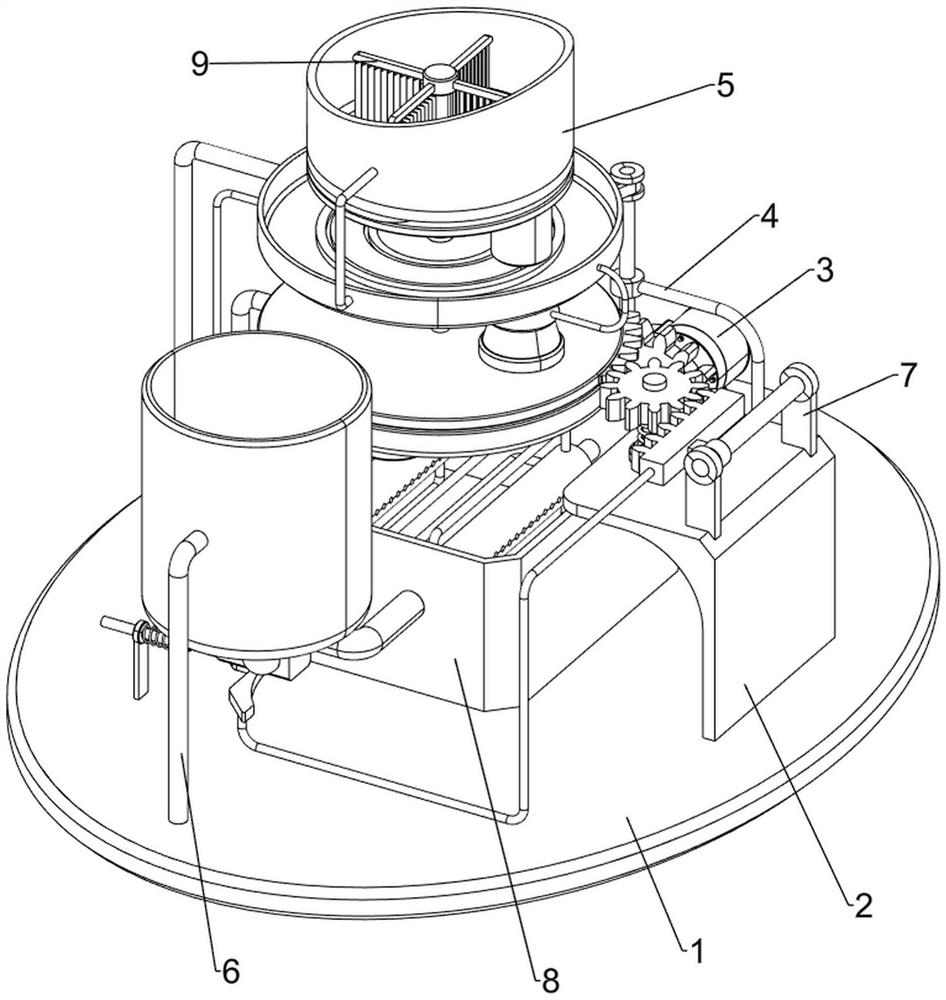
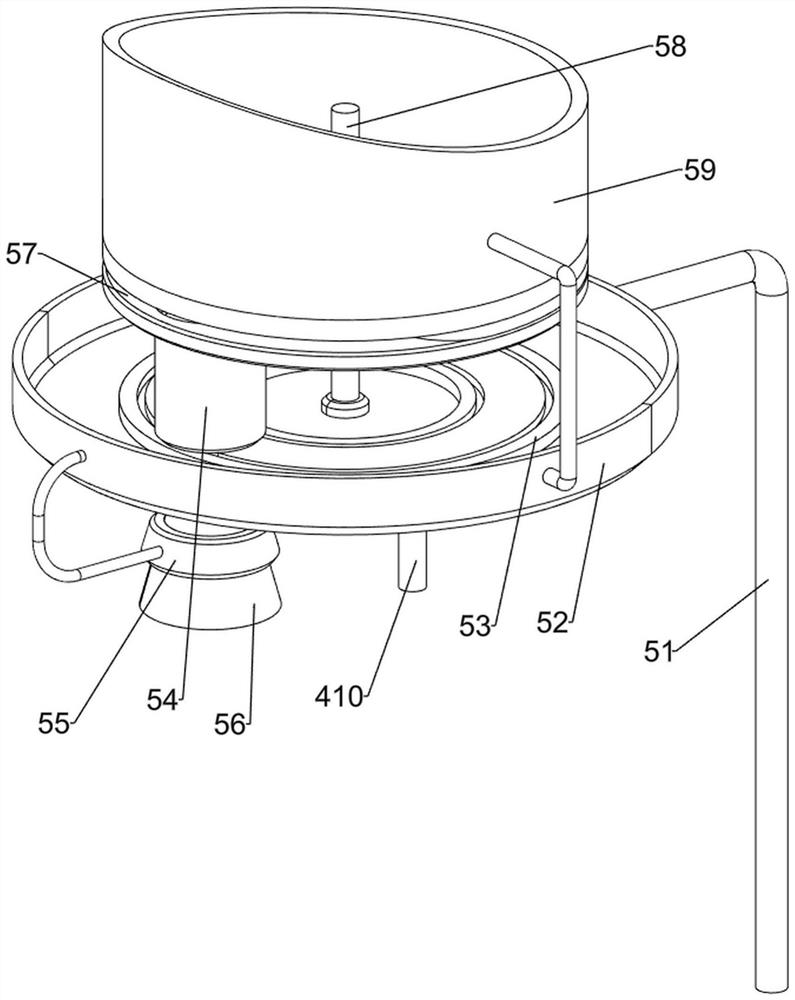
[0089] Such as figure 1 As shown, a grinding processing equipment for ceramic production raw materials includes a bottom plate 1, a workbench 2, a motor 3, a grinding mechanism 4 and a feeding mechanism 5, a workbench 2 is provided in the middle of the upper right side of the bottom plate 1, and the upper rear side of the bottom plate 1 is Motor 3 is installed, and base plate 1 upper rear side is provided with grinding mechanism 4, and grinding mechanism 4 is connected with motor 3 output shafts, and base plate 1 upper left side is provided with unloading mechanism 5, and unloading mechanism 5 is connected with grinding mechanism 4.
[0090] When it is necessary to grind the ceramic production raw materials into powder, this kind of grinding processing equipment can be used. First, people pour the mixed ceramic production raw materials into the feeding mechanism 5, start the motor 3, and the output shaft of the motor 3 drives the grinding mechanism 4 to operate. The mechanism ...
Embodiment 2
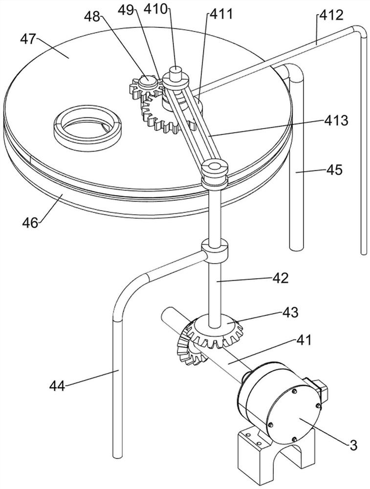
[0092] On the basis of Example 1, such as Figure 2-Figure 4 As shown, the grinding mechanism 4 includes a first rotating shaft 41, a second rotating shaft 42, a bevel gear set 43, a first fixed column 44, a second fixed column 45, a discharge plate 46, a grinding plate 47, a third rotating shaft 48, a Straight gear 49, fourth rotating shaft 410, first missing gear 411, third fixed column 412 and transmission assembly 413, first rotating shaft 41 is provided on the output shaft of motor 3, and first fixed Column 44, the upper part of the first fixed column 44 is rotatably provided with a second rotating shaft 42, a bevel gear set 43 is arranged between the lower part of the second rotating shaft 42 and the front part of the first rotating shaft 41, and a second fixed shaft is arranged in the middle part on the left side of the bottom plate 1. Column 45, the top of the second fixed column 45 is provided with a discharge plate 46, the top of the discharge plate 46 is rotatably p...
Embodiment 3
[0097] On the basis of Example 2, such as Figure 5-Figure 9 Shown, also include manual water spraying mechanism 6, base plate 1 upper front left side is provided with manual water spraying mechanism 6, and manual water spraying mechanism 6 includes the 5th fixing column 61, water tank 62, first water pipe 63, the second Water pipe 64, the 6th fixed post 65, linear spring 66, pull bar 67, baffle plate 68 and movable box 69, bottom plate 1 upper front part left side is provided with the 5th fixed post 61, and the fifth fixed post 61 top is provided with water tank 62, The middle of the bottom of the water tank 62 is provided with a first water pipe 63, and the left and right sides of the first water pipe 63 rear end are rotatably provided with a second water pipe 64. The upper sliding type is provided with a pull rod 67, and a linear spring 66 is wound on the pull rod 67. The two ends of the linear spring 66 are connected with the sixth fixed column 65 and the pull rod 67 respe...
PUM
 Abstract
Description
Claims
Application Information
 - R&D
- Intellectual Property
- Life Sciences
- Materials
- Tech Scout
- Unparalleled Data Quality
- Higher Quality Content
- 60% Fewer Hallucinations
Browse by: Latest US Patents, China's latest patents, Technical Efficacy Thesaurus, Application Domain, Technology Topic, Popular Technical Reports.
© 2025 PatSnap. All rights reserved.Legal|Privacy policy|Modern Slavery Act Transparency Statement|Sitemap|About US| Contact US: help@patsnap.com


