AO combined enhanced nitrogen and carbon removal device with built-in MBR

A denitrification and inner cavity technology, applied in chemical instruments and methods, water/sewage multi-stage treatment, water/sludge/sewage treatment, etc., to achieve the effects of increasing sludge return flow, improving aeration efficiency, and reducing costs

Active Publication Date: 2021-03-09
恩宜瑞(江苏)环境发展有限公司
View PDF6 Cites 0 Cited by
  • Summary
  • Abstract
  • Description
  • Claims
  • Application Information

AI Technical Summary

Problems solved by technology

However, the MBR membrane requires a separate membrane tank, which requires an independent floor space, which limits its industrial application to a certain extent.

Method used


Image

  • AO combined enhanced nitrogen and carbon removal device with built-in MBR
  • AO combined enhanced nitrogen and carbon removal device with built-in MBR
  • AO combined enhanced nitrogen and carbon removal device with built-in MBR

Examples


Embodiment 1

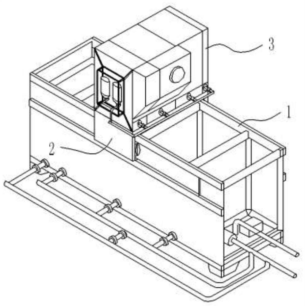
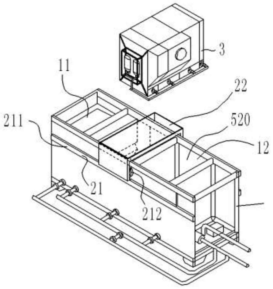
[0026] Embodiment 1: as figure 1 , 2 The AO combination enhanced denitrification and carbon removal device with built-in MBR is shown, including a box body, and a pretreatment unit is set inside the box body for pre-treatment of wastewater, and is set inside the box body to treat the pretreatment unit. The advanced treatment unit for reprocessing wastewater; the box body includes a first installation box 1, a mobile installation part 2 installed on the first box body 1, and a second mobile installation part 2 installed on the first box body 1 Box 3;

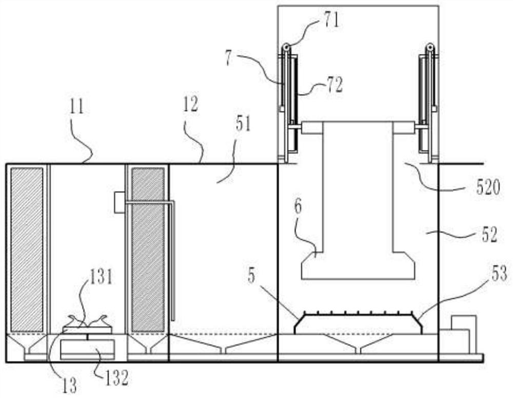
[0027] Such as image 3 As shown, the first box 1 includes a pretreatment chamber 11 and an AO treatment chamber 12 connected in sequence;

[0028] Such as Figure 4 As shown, the pretreatment unit is arranged in the pretreatment chamber 11; the pretreatment unit includes a partition cylinder 41 installed in the pretreatment chamber 11, and a mounting plate for installing the partition cylinder 41 on the inner wall of the pre...

Embodiment 2

[0036] Embodiment 2: The difference from Embodiment 1 is that the first filter cavity 113, the second filter cavity 114, the third filter cavity 115, the fourth filter cavity 116, and the inner cavity 111 are connected in sequence, and the connecting points are respectively provided with first Filter, second filter, third filter, fourth filter; the aperture ratio of the first filter, second filter, third filter, and fourth filter is 3:2:1:0.8 .

Embodiment 3

[0037] Embodiment 3: different from Embodiment 1: as Figure 6 As shown, the chain lifting mechanism 71 includes a mounting rod 711 installed on the side wall of the second box body 3, a chain shaft 712 that is movably arranged on the upper end of the mounting rod 711, a power mechanism 713 installed on the mounting rod 711, and one end is fixedly installed on the On the power mechanism 713, the other end passes through the chain 714 of the chain shaft 712; the mounting part 72 includes a sliding frame 721 installed on the outside of the mounting bar 711, and a fixed frame 722 movably installed on the sliding frame 721; the other end of the chain 714 is fixed On the fixed frame 722.


PUM


Abstract

The invention provides an AO combined enhanced nitrogen and carbon removal device with a built-in MBR. The AO combined enhanced nitrogen and carbon removal device comprises a box body, a pretreatmentunit arranged in the box body and used for carrying out earlier-stage treatment on wastewater, and a deep treatment unit arranged in the box body and used for carrying out retreatment on the wastewater treated by the pretreatment unit, wherein the deep treatment unit comprises an AO treatment unit and an MBR treatment unit. According to the invention, the AO combined enhanced nitrogen and carbon removal device is reasonable in overall structural design, the MBR membrane assembly is selectively placed in the AO process for use through the lifting unit, the sludge reflux quantity and the sludgeconcentration in the AO process can be effectively increased, and the SS concentration of effluent can be reduced, so that the denitrification and decarbonization effects can be effectively enhanced;and the AO combined enhanced nitrogen and carbon removal device has the advantages of high efficiency, small occupied area, low investment cost and the like, and has a good application prospect.

Description

technical field [0001] The invention relates to the technical field of wastewater treatment equipment, in particular to an AO combination enhanced nitrogen and carbon removal device with a built-in MBR. Background technique [0002] In recent years, with the rapid development of my country's national economy and the improvement of people's living standards, the problem of water pollution has become increasingly severe. Among them, organic matter and nitrogen-containing pollutants are more prominent. These pollutants are not discharged up to the standard, leading to eutrophication of water bodies in large areas, causing serious water ecological disasters and secondary disasters, and bringing huge environmental pollution to the country. and economic loss. To this end, the country has successively issued more stringent laws and regulations to limit the discharge of such wastewater. Therefore, the development of efficient organic matter removal and denitrification treatment pr...

Claims


Application Information

Patent Timeline
Patent Type & Authority Applications(China)
IPC IPC(8): C02F9/14
CPCC02F1/001C02F3/30Y02W10/10
Inventor 徐敬生郭志成陈振徐慧娟黄前霖吕路
Owner 恩宜瑞(江苏)环境发展有限公司
Why Eureka
Try Eureka