A fixture for photovoltaic cell electroplating

A technology of photovoltaic cells and fixtures, applied in circuits, electrolytic components, electrolytic processes, etc., can solve the problems of complex automatic upper and lower silicon wafer devices, easy damage and fragmentation of silicon wafers, etc., to improve the uniformity of electroplating, improve work efficiency, Practical effect

Active Publication Date: 2021-11-05
SUZHOU SUNWELL NEW ENERGY CO LTD
View PDF7 Cites 0 Cited by
  • Summary
  • Abstract
  • Description
  • Claims
  • Application Information

AI Technical Summary

Problems solved by technology

[0003] Existing electroplating methods for photovoltaic cells include horizontal plating, vertical continuous plating, and rack plating. Horizontal plating usually does not require the use of fixtures. The non-plated surface of photovoltaic cells is connected to the cathode of an external power supply through a brush or a vacuum chuck. The closed circuit of power cathode-silicon wafer-plating solution-power anode is completed through the silicon wafer itself. This method of electroplating is usually suitable for single-sided electroplating of photovoltaic cells. The vertical continuous plating fixture is usually fixed on the transmission system to hold the silicon One side of the wafer goes through a series of cleaning and electroplating tanks with the transmission system, and the current is conducted on the surface of the silicon wafer from the clamping place of the conductive fixture to the far end. This method can support simultaneous electroplating on both sides of the silicon wafer, but vertically continuous Plating usually requires the arrangement of anodes in the tank and the design changes of the tank itself to optimize the uniformity of current distribution on the surface of the silicon wafer and overcome the resistance of conduction along the surface of the silicon wafer. The fixture for rack plating is usually slightly larger than the silicon wafer. The frame-type device clamps the four sides of the silicon wafer and energizes several clamping points evenly distributed on the surface of the silicon wafer. The plating uniformity of this method is better than that of vertical continuous plating, but the automatic upper and lower silicon wafer device is more complicated. And silicon wafers are prone to defects such as damage, fragments, and cracks

Method used


Image

  • A fixture for photovoltaic cell electroplating
  • A fixture for photovoltaic cell electroplating
  • A fixture for photovoltaic cell electroplating

Examples


Embodiment Construction

[0024] The following will clearly and completely describe the technical solutions in the embodiments of the present invention with reference to the accompanying drawings in the embodiments of the present invention. Obviously, the described embodiments are only some, not all, embodiments of the present invention. Based on the embodiments of the present invention, all other embodiments obtained by persons of ordinary skill in the art without making creative efforts belong to the protection scope of the present invention.

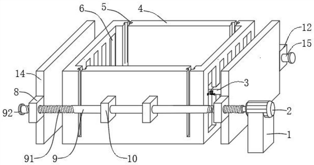
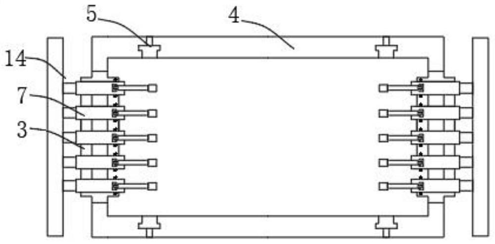
[0025] see Figure 1-5 , the present invention provides a technical solution: a fixture for photovoltaic cell electroplating, including a flower basket 4 and a motor 2, the side of the motor 2 is fixedly connected to the fixing seat 1, the output shaft of the motor 2 is fixedly connected to one end of the rotating shaft 9, and the rotating shaft 9 is far away from the motor 2 One end is fixedly connected with the limited disk 92, and the peripheral side of the...


PUM


Abstract

The invention discloses a fixture for photovoltaic cell electroplating, which includes a flower basket and a motor. The peripheral side of the motor is fixedly connected to a fixing seat, the output shaft of the motor is fixedly connected to one end of a rotating shaft, and the end of the rotating shaft away from the motor is fixedly connected to a limiting disk. , the rotating shaft is provided with an external thread on the peripheral side near the end, and is screwed to the inside of the first fixed block, the first fixed block is fixedly installed on one side of the movable plate, and the other side of the movable plate is fixedly connected to the second fixed block. block, the inside of the second fixed block is slidably connected with a slide bar, and the middle part of the rotating shaft and the slide bar is connected to the limit seat, and the limit seat is fixedly installed on the outside of the flower basket. The chute, the inner side of the chute is slidably connected to the slider, and the clamping block is used to clamp and fix the surface, which is conducive to improving the uniformity of electroplating, so that the clamping force is evenly distributed on the surface of the silicon wafer, and the silicon wafer is prevented from being damaged by the clamp. Fragments, hidden cracks.

Description

technical field [0001] The invention relates to the technical field of solar cells and semiconductor manufacturing, in particular to a fixture for photovoltaic cell electroplating. Background technique [0002] Crystalline silicon solar cells usually use screen printing silver paste and then sintered at high temperature or low temperature to form metal electrodes to export photogenerated carriers, which is currently the most widely used metallization method for crystalline silicon solar cells. This method has a simple process and is currently the mainstream mass production process. In recent years, with the continuous development of silicon wafer and battery technology, the production cost of solar cells has continued to decline, and the cost of expensive silver paste in the metallization process is the largest in the entire battery cost. The proportion of the silver electrode is constantly increasing, and the width and aspect ratio of the silver electrode are limited by the...

Claims


Application Information

Patent Timeline
Patent Type & Authority Patents(China)
IPC IPC(8): C25D7/12C25D17/06H01L31/18H01L21/687
CPCC25D7/12C25D17/001C25D17/06H01L21/687H01L31/18Y02P70/50
Inventor 姚宇李中天
Owner SUZHOU SUNWELL NEW ENERGY CO LTD
Why Eureka
Try Eureka