Automatic steel cylinder welding device

An automatic welding and steel cylinder technology, which is used in grinding drive devices, grinding/polishing safety devices, grinding machines, etc., can solve problems such as low welding efficiency, ensure welding quality, improve welding efficiency, and facilitate operation. Effect

Active Publication Date: 2021-03-12
贵州西南装备制造有限公司
View PDF8 Cites 2 Cited by
  • Summary
  • Abstract
  • Description
  • Claims
  • Application Information

AI Technical Summary

Problems solved by technology

[0005] Aiming at the deficiencies in the prior art, the technical problem solved by the present invention is to provide an automatic steel cylinder welding device to solve the problem of low welding efficiency caused by manual rotary welding of welders

Method used


Image

  • Automatic steel cylinder welding device
  • Automatic steel cylinder welding device
  • Automatic steel cylinder welding device

Examples


Embodiment Construction

[0029] The following is further described in detail through specific implementation methods:

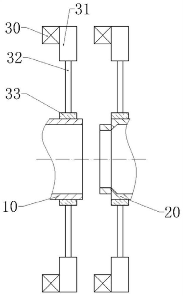
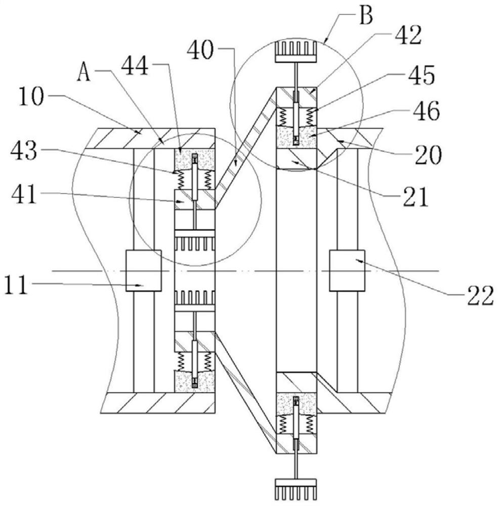
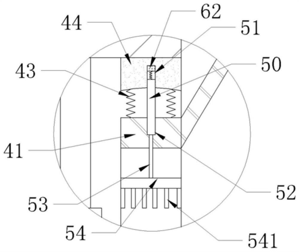
[0030] The reference signs in the drawings of the specification include: the first steel cylinder 10, the first fan blade 11, the second steel cylinder 20, the receiving ring 21, the second fan blade 22, the motor 30, the hydraulic cylinder 31, the telescopic shaft of the hydraulic cylinder 32. Arc plate 33, connecting cylinder 40, first fixed ring 41, second fixed ring 42, first spring 43, first grinding block 44, second spring 45, second grinding block 46, first sliding rod 50 , the first groove 51, the second groove 52, the first connecting rod 53, the first cooling plate 54, the first cooling fin 541, the third groove 55, the fourth groove 56, the second connecting rod 57, the first The second heat sink 58 , the second heat sink 581 , the second sliding rod 59 , the coil 60 , the magnet 61 , the first electromagnet 62 , and the second electromagnet 63 .

[0031] The embodiment i...


PUM


Abstract

The invention relates to the technical field of prestressed steel cylinder concrete pipes, and particularly discloses an automatic steel cylinder welding device. The automatic steel cylinder welding device comprises a rack, driving mechanisms and a grinding cylinder. The driving mechanisms comprise motors and hydraulic cylinders and need to be used in pairs. The two paired driving mechanisms are located on the two sides of steel cylinders correspondingly and oppositely arranged. The grinding cylinder is fixed to the rack and comprises a first fixed ring and a second fixed ring. The first fixedring is coaxially placed in one of the steel cylinders, and the outer side wall of the first fixed ring is connected with a first grinding block. The second fixed ring coaxially sleeves the peripheryof a bearing ring of the other steel cylinder, the inner side wall of the second fixed ring is connected with a second grinding block, and the second grinding block abuts against the periphery of thebearing ring of the other steel cylinder. The automatic steel cylinder welding device aims to solve the problem of low welding efficiency caused by manual rotary welding of a welder.

Description

technical field [0001] The invention relates to the technical field of prestressed steel cylinder concrete pipes, in particular to an automatic welding device for steel cylinders. Background technique [0002] Prestressed Concrete Cylinder Pipe (PCCP for short) is made by winding a hoop prestressed steel wire on a high-strength concrete tube core with a steel cylinder, and then spraying a dense cement mortar protective layer on it. of water pipes. It is a composite pipe composed of thin steel plate, high-strength steel wire and concrete. It fully and comprehensively exerts the tensile strength and easy sealing of steel and the compression and corrosion resistance of concrete. It has high sealing performance, high strength and high resistance. seepage characteristics. [0003] The PCCP steel liner is limited by the caliber in the production process. The continuous spiral coil welding machine is used to make the steel tube, and then assembled by the assembly machine. The ass...

Claims


Application Information

Patent Timeline
IPC IPC(8): B24B5/04B24B5/10B24B27/00B24B47/00B24B55/02
CPCB24B5/04B24B5/10B24B27/0023B24B27/0076B24B55/02B24B47/00
Inventor 金仕文黄晓朋向冰
Owner 贵州西南装备制造有限公司
Why Eureka
Try Eureka