
A visual 3D pick-and-place method and system based on collaborative robots

A robot and visual technology, applied in the field of visual 3D pick-and-place, can solve the problems of high production difficulty, difficulty in coping with scene lighting changes, occlusion and stacking, high upper limit of installation and use, and achieve strong anti-environmental light interference ability, guarantee reliability and high efficiency performance, satisfying the effect of system measurement accuracy

Active Publication Date: 2021-12-28
新拓三维技术(深圳)有限公司
View PDF0 Cites 0 Cited by
  • Summary
  • Abstract
  • Description
  • Claims
  • Application Information

AI Technical Summary

Problems solved by technology

[0004] Most of the existing visual perception processes can only be used for 2D pose estimation of flat single-target objects, which are easily affected by factors such as lighting and background environment, and are difficult to cope with actual situations such as scene lighting changes, occlusion stacking, etc.
At present, the visual perception system based on deep learning method that has made great progress has a long production cycle and high difficulty in making network training data sets; at the same time, the network model has weak generalization ability and low robustness, which is not conducive to practical application. indoor scene
[0005] However, for existing robot systems, the upper limit of installation and use is high, the programming process is cumbersome, human-machine cooperation is not emphasized, the trajectory is mostly taught manually, without trajectory planning, the operation efficiency is low, and the reliability is poor. Job failed, can only be used in structured environments
[0006] There is a lack of an automated and intelligent pick-and-place system based on collaborative robots and high-precision vision algorithms in the prior art

Method used


Image

  • A visual 3D pick-and-place method and system based on collaborative robots
  • A visual 3D pick-and-place method and system based on collaborative robots
  • A visual 3D pick-and-place method and system based on collaborative robots

Examples


Embodiment Construction

[0040] In order to make the technical problems, technical solutions and beneficial effects to be solved by the embodiments of the present invention clearer, the present invention will be further described in detail below in conjunction with the accompanying drawings and embodiments. It should be understood that the specific embodiments described here are only used to explain the present invention, not to limit the present invention.

[0041] It should be noted that when an element is referred to as being “fixed” or “disposed on” another element, it may be directly on the other element or be indirectly on the other element. When an element is referred to as being "connected to" another element, it can be directly connected to the other element or indirectly connected to the other element. In addition, the connection can be used for both fixing function and circuit communication function.

[0042] It is to be understood that the terms "length", "width", "top", "bottom", "front"...


PUM


Abstract

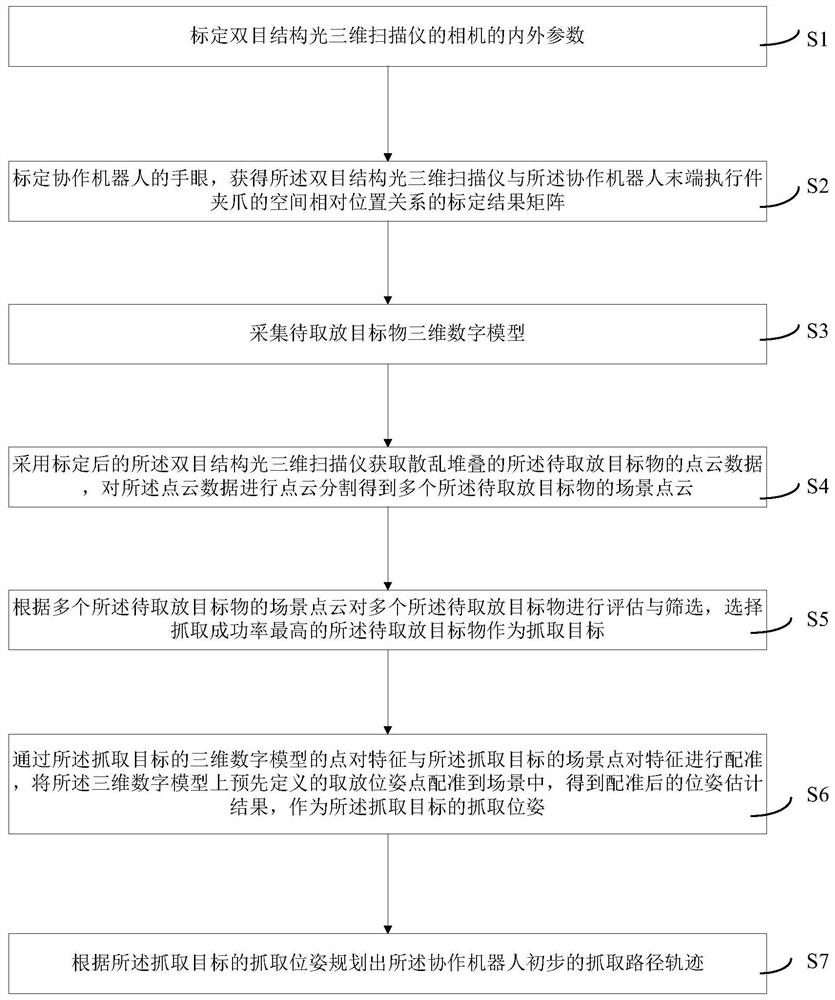
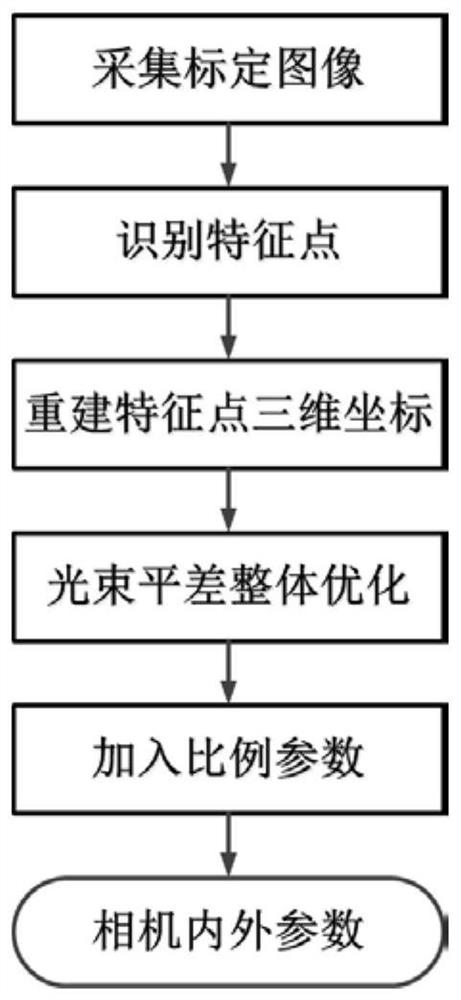
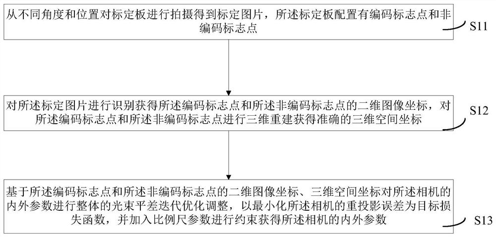
The present invention provides a visual 3D pick-and-place method and system based on a collaborative robot. The method includes: calibrating the internal and external parameters of a camera of a binocular structured light three-dimensional scanner; calibrating the hand-eye of a collaborative robot to obtain a calibration result matrix; collecting objects to be picked and placed The 3D digital model of the object; the calibrated binocular structured light 3D scanner is used to obtain the point cloud data of the scattered and stacked objects to be picked and placed, and the point cloud is segmented to obtain multiple scene point clouds of the objects to be picked and placed; according to The scene point cloud of multiple objects to be picked and placed selects the object to be picked and placed with the highest grasping success rate as the grasping target; through the registration of the 3D digital model of the captured target with the features of the scene point, the pre- The defined pick-and-place pose points are registered to the scene, and the registered pose estimation results are obtained as the grasping pose of the grasping target; the preliminary grasping path trajectory of the collaborative robot is planned. It can accurately identify the target object, and the grasping and positioning accuracy is high.

Description

technical field [0001] The invention relates to the technical field of visual 3D pick-and-place, in particular to a visual 3D pick-and-place method and system based on a collaborative robot. Background technique [0002] With the automation and intelligence of industrial manufacturing and logistics transportation, the industrial robot pick-and-place system with multi-sensor integration is the core force in the future automated intelligent manufacturing and intelligent logistics fields. At present, the industrial robot pick-and-place system is mainly used in the fields of workpiece assembly, material loading, product handling, object sorting, defect detection, and packaging. In the traditional structured environment, the robot pick-and-place system that performs single repetitive operations through offline programming cannot complete the scattered stacking of target objects, and at the same time, it cannot estimate the pose of the captured target in the scene. It is just a gr...

Claims


Application Information

Patent Timeline
Patent Type & Authority Patents(China)
IPC IPC(8): B25J9/16G06T7/246G06T7/80
CPCB25J9/1697B25J9/1682G06T7/246G06T7/80
Inventor 唐正宗赵建博冯超宗玉龙
Owner 新拓三维技术(深圳)有限公司
Learn More