Forming process of combined and re-fused injection molded part with metal insert

A metal insert and molding process technology, applied in the field of metal insert plastic part molding process, can solve the problems of incomplete plastic cladding metal, slow injection molding speed, affecting mold temperature, etc., to improve product quality and product molding. The effect of improving the speed, plastic injection speed, and improving molding efficiency

Inactive Publication Date: 2021-03-12
袁月
View PDF6 Cites 0 Cited by
  • Summary
  • Abstract
  • Description
  • Claims
  • Application Information

AI Technical Summary

Problems solved by technology

[0003] 1) The metal covered by plastic is incomplete, and the plastic cannot be tightly bonded to the metal part due to air bubbles and turbulence, and the whole part contains air bubbles or even separates;
[0004] 2) The speed of injection molding needs to be slowed down. Metal parts are easy to absorb heat when placed in the mold and affect the mold temperature. It is necessary to wait for the mold temperature to balance, and the processing time will slow down;

Method used


Image

  • Forming process of combined and re-fused injection molded part with metal insert
  • Forming process of combined and re-fused injection molded part with metal insert

Examples


Embodiment 1

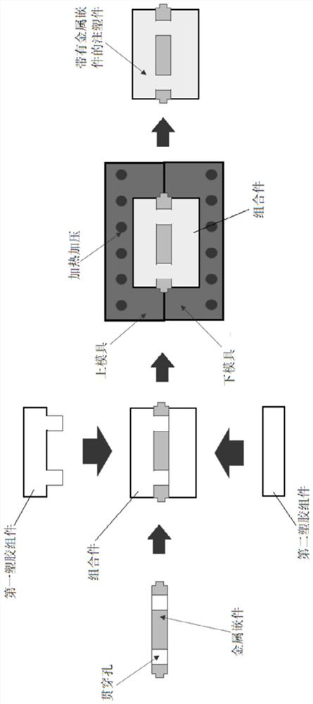
[0023] Please refer to figure 2 , the present embodiment is a combined and refused injection molding process with metal inserts, which includes the following steps:

[0024] 1) Injection molding the first plastic component;

[0025] 2) Injection molding the second plastic component, the second plastic component is assembled with the first plastic component to form a storage cavity that can accommodate the metal insert;

[0026] 3) Combining the metal insert with the first plastic component and the second plastic component to form an assembly, and the assembly is consistent with the shape of the designed product;

[0027] 4) The assembly is heated and pressurized in the mold, so that the contact surfaces of the first plastic component and the second plastic component are fused to form an integral part, and an injection molded part with a metal insert is obtained after cooling.

[0028] The molding plastic of the first plastic component and the second plastic component is the...

Embodiment 2

[0036] This embodiment is a combined and refused injection molded part molding process with metal inserts, which includes the following steps:

[0037] 1) Injection molding the first plastic component;

[0038] 2) Injection molding the second plastic component;

[0039] 3) Injection molding the third plastic component, the third plastic component, the second plastic component and the first plastic component are combined and assembled to form a storage cavity that can accommodate the metal insert;

[0040] 3) Combining the metal insert with the first plastic component, the second plastic component, and the third plastic component to form an assembly, and the assembly is consistent with the shape of the designed product;

[0041] 4) Heat and press the assembly in the mold, so that the contact surfaces between the first plastic component, the second plastic component and the third plastic component are fused to form a whole, and a metal Injection molded parts for inserts.

[0...


PUM

PropertyMeasurementUnit
Particle sizeaaaaaaaaaa
Sizeaaaaaaaaaa

Abstract

The invention discloses a forming process of a combined and re-fused injection molded part with a metal insert. The forming process comprises the following steps that firstly, injection molding is conducted to form multiple plastic assemblies independently, and all the plastic assemblies are combined and assembled to form a storage cavity capable of containing the metal insert; secondly, the metalinsert and the plastic assemblies are combined to form an assembly, wherein the assembly and a designed product are of the consistent structure; and thirdly, heating and pressurizing are conducted onthe assembly in a mold, and therefore the contact surfaces of all the plastic assemblies can be fused to form an integral plastic part, and the injection molded part with the metal insert is obtainedafter cooling. By means of the forming process, the problems of bubbles and turbulent flow appearing in the direct embedding forming process of an existing insert type plastic part can be effectivelyavoided, the forming efficiency is greatly improved, the production efficiency is improved, the cost is reduced, and the product quality is improved.

Description

technical field [0001] The invention belongs to the technical field of molding plastic parts with metal inserts, and in particular relates to a combined and refused injection molded parts molding process with metal inserts. Background technique [0002] In the past, the method of inserting metal parts into plastics was to directly open a plastic insert injection mold (Insert mold), and place the metal parts in the cavity of the metal mold for plastic insert injection. The molten plastic directly fills the mold cavity through the pressure output by the injection screw, and covers the metal parts. After cooling, it forms a single part and takes it out of the mold cavity. The molding process is as follows: figure 1 shown. figure 1 Shown is the molding process of embedded injection of metal parts in the prior art, which has the following defects: [0003] 1) The metal covered by plastic is incomplete, and the plastic cannot be tightly bonded to the metal part due to air bubble...

Claims


Application Information

Patent Timeline
IPC IPC(8): B29C69/00B29C65/44
CPCB29C69/00B29C65/44B29C66/742
Inventor 袁月
Owner 袁月
Why Eureka
Try Eureka