Composite material tube forming tool system

A technology for composite material pipes and forming tooling, which is applied to tubular objects, household appliances, and other household appliances. It can solve the problems of difficult manufacturing of composite material pipes, complex working conditions, and complex layering, and achieve smooth surface quality and guaranteed The effect of high molding quality and surface quality

Pending Publication Date: 2021-03-12
NANJING DONGJU CARBON FIBER COMPOSITE RES INST CO LTD +1
View PDF7 Cites 0 Cited by
  • Summary
  • Abstract
  • Description
  • Claims
  • Application Information

AI Technical Summary

Problems solved by technology

[0005] The invention provides a composite material pipe forming tooling system, aiming to solve the problem of difficulty in manufacturing composite material pipes with the characteristics of complex working conditions, complex layering, tapered structure, and large size (length exceeding 6m).

Method used


Image

  • Composite material tube forming tool system
  • Composite material tube forming tool system
  • Composite material tube forming tool system

Examples


Embodiment

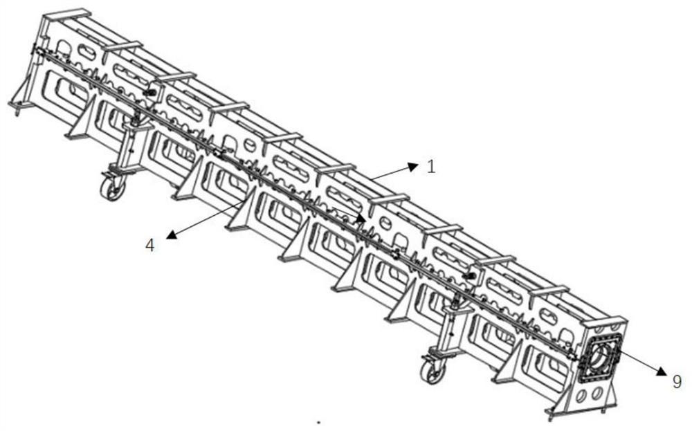
[0041] Such as Figure 3-14 As shown, a composite material pipe forming tooling system includes an upper mold body 1, a lower mold body 4, a cover plate 9 and an L-shaped auxiliary paving tooling 12; the end faces of the upper mold body 1 and the lower mold body 4 are provided There is a first sealing groove 2 for placing the first sealing strip 15, and the second sealing groove 5 for placing the second sealing strip 16 is arranged on the flange surface of the lower mold body 4, and the flange surface of the lower mold body 4 There are some first exhaust grooves 18 communicated with the cavity of the lower mold body 4, the second exhaust grooves 19 are communicated with the first exhaust grooves 18, and the top of the upper mold body 1 is provided with the second exhaust grooves 19. A number of connected vacuum quick connectors 3; the vertical surface of the auxiliary paving tool 12 is provided with a number of lost layer marking lines 13, when laying prepreg sheets in the cav...


PUM


Abstract

The invention discloses a composite material tube forming tool system, and belongs to the field of unmanned aerial vehicle composite tubes. The composite material tube forming tool system is mainly used for solving the problem that the composite material tube with the characteristics of complex working conditions, complex paving layers, a conical structure, a large size (the length exceeding 6m) and the like is high in manufacturing difficulty. The forming tool system mainly comprises an upper die body, a lower die body, a cover plate and an auxiliary paving tool, wherein the upper die body and the lower die body are both of a female die structure, and a frame welding structure is adopted; the cover plate is of a flat plate structure, and a putty strip pasting area and connecting bolt holes are designed in the cover plate; the auxiliary paving tool is of an L-shaped structure and connected to the upper die body and the lower die body through positioning pins and bolts, and the auxiliary paving tool is equipped with a paving identification line used for identifying layer loss and paving of prepregs. The forming tool system is particularly suitable for manufacturing conical and large-size (the length exceeding 6 m) carbon fiber composite tubes.

Description

technical field [0001] The invention relates to a molding tooling system for composite material pipes, which belongs to the field of UAV composite material pipes, and is mainly used for composite material pipes with complex working conditions, complex layering, conical structure, and large size (more than 6m). Create difficult problems. Background technique [0002] Carbon fiber is an ideal material for structural design due to its excellent properties of low density, high specific strength and high specific modulus; figure 1 As shown, the carbon fiber composite material tube is a typical structure in the product structure design, and is often used in the wing spar, tail support tube, empennage main beam, rudder surface main beam and other important structural areas of UAVs. Carbon fiber is a special material whose tensile properties are far greater than compressive properties. In the manufacturing process of carbon fiber composite products, it is necessary to avoid problem...

Claims


Application Information

Patent Timeline
IPC IPC(8): B29C70/34B29L23/00
CPCB29C70/342B29C70/345B29L2023/22
Inventor 李颖华王明军秦友山
Owner NANJING DONGJU CARBON FIBER COMPOSITE RES INST CO LTD
Why Eureka
Try Eureka