
Efficient centrifugal pump energy efficiency management method and system

An energy efficiency management and centrifugal pump technology, which is applied in the field of efficient centrifugal pump energy efficiency management methods and systems, can solve the problem that the energy consumption and efficiency of centrifugal pumps cannot be obtained, the high-efficiency area of ​​each pump operating condition cannot be guaranteed, and the machine cannot be quickly and accurately judged. Pump and other problems, to achieve the effect of elevator pump integrity rate and operating energy efficiency

Active Publication Date: 2021-03-12
ZHEJIANG SUPCON TECH
View PDF6 Cites 4 Cited by
  • Summary
  • Abstract
  • Description
  • Claims
  • Application Information

AI Technical Summary

Problems solved by technology

[0010] 1. At present, the energy consumption management of pumps mainly comes from the current data of pumps in the electrical system. The operation process and equipment data of on-site pumps come from the basic automatic control system (BPCS). If data interaction is not realized between different platforms, the real-time energy consumption and efficiency of centrifugal pumps cannot be achieved. Obtain
[0011] 2. The pump has mechanical power consumption, hydraulic power consumption, volume loss power consumption and other factors, the effective power of the pump is less than the actual motor power, and the real-time effective power of the pump is not available
[0012] 3. The performance curve of the centrifugal pump can only be found in the archived data of the factory equipment, and cannot be integrated and displayed with the SCADA control system. The operator cannot quickly and accurately judge whether the real-time status of the pump is in the high-efficiency zone
[0013] 4. The initial working conditions of the pump operation and the working conditions under long-term operation cannot be recorded and judged, which is not conducive to the operation and maintenance of the equipment
[0014] 5. When multiple pumps are connected in parallel or in series, it is impossible to ensure that the working conditions of each pump are running in the high-efficiency zone, resulting in energy waste

Method used


Image

  • Efficient centrifugal pump energy efficiency management method and system

Examples


Embodiment Construction

[0047] The present invention will be described in detail below in conjunction with specific embodiments. The following examples will help those skilled in the art to further understand the present invention, but do not limit the present invention in any form. It should be noted that those skilled in the art can make several changes and improvements without departing from the concept of the present invention. These all belong to the protection scope of the present invention.

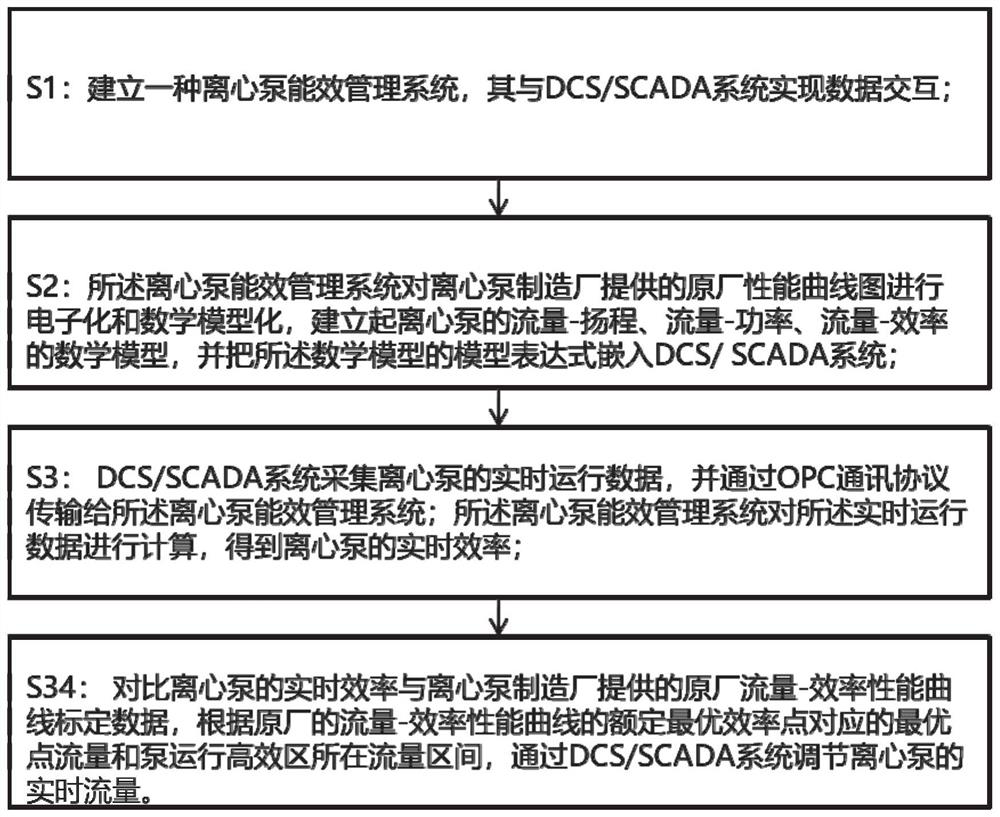
[0048] Such as figure 1 , this embodiment discloses a high-efficiency centrifugal pump energy efficiency management method, including the following steps:

[0049] S1: Establish a centrifugal pump energy efficiency management system, which realizes data interaction with the DCS / SCADA system. The centrifugal pump energy efficiency management system includes:

[0050] The electronic and mathematical modeling module is used to electronically and mathematically model the original performance curve provided b...


PUM


Abstract

The invention provides an efficient centrifugal pump energy efficiency management method. The comprises the following steps that S1, a centrifugal pump energy efficiency management system is established, and data interaction is achieved between the centrifugal pump energy efficiency management system and a DCS / SCADA system; S2, the centrifugal pump energy efficiency management system carries out electronization and mathematical modeling on an original factory performance curve graph, a mathematical model of the flow-lift, the flow-power and the flow-efficiency of a centrifugal pump is established, and a model expression of the mathematical model is embedded into a DCS / SCADA system; S3, the DCS / SCADA system collects real-time operation data of the centrifugal pump and transmits the real-time operation data to the centrifugal pump energy efficiency management system through an OPC communication protocol, and the centrifugal pump energy efficiency management system calculates the real-time operation data to obtain the real-time efficiency of the centrifugal pump; and S4, the real-time efficiency of the centrifugal pump is compared with original factory flow-efficiency performance curve calibration data, and the real-time flow of the centrifugal pump is adjusted through the DCS / SCADA system.

Description

technical field [0001] The invention relates to a centrifugal pump, in particular to a high-efficiency centrifugal pump energy efficiency management method and system. Background technique [0002] Centrifugal pump is a kind of mechanical equipment used to transport liquid medium, which is widely used in chemical industry, water affairs, pipeline transportation and other production. The centrifugal pump is driven by a motor. The pump body and the suction pipe are filled with liquid. The motor drives the impeller to rotate at high speed, and the impeller drives the liquid between the blades to rotate together. Due to the centrifugal force, the liquid is thrown from the center of the impeller to the outer edge of the impeller and is relatively The high pressure flows out along the discharge port. At the same time, a certain vacuum is formed at the center of the impeller due to the liquid being thrown out, and the pressure at the inlet liquid level is higher than that at the ce...

Claims


Application Information

Patent Timeline
IPC IPC(8): F04D15/00G06F30/20
CPCF04D15/00G06F30/20
Inventor 鲁勋张宏伟马楠桦李朦
Owner ZHEJIANG SUPCON TECH
Learn More