Wood drying and preservative treatment device
A technology for anti-corrosion treatment and wood drying, which is applied in the processing of dry goods, the arrangement of dry gas, and the drying of solid materials. Effect
- Summary
- Abstract
- Description
- Claims
- Application Information
AI Technical Summary
Problems solved by technology
Method used
Image

Examples
Embodiment
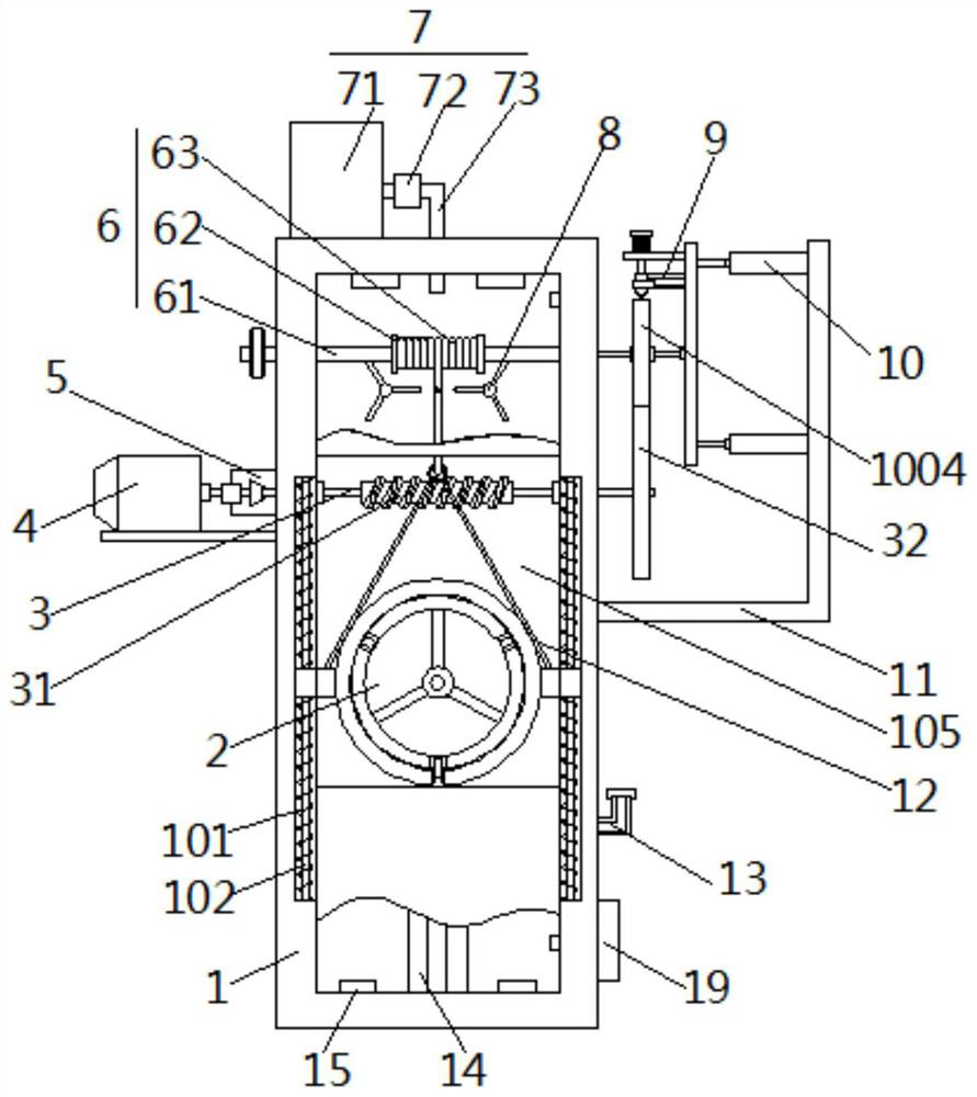
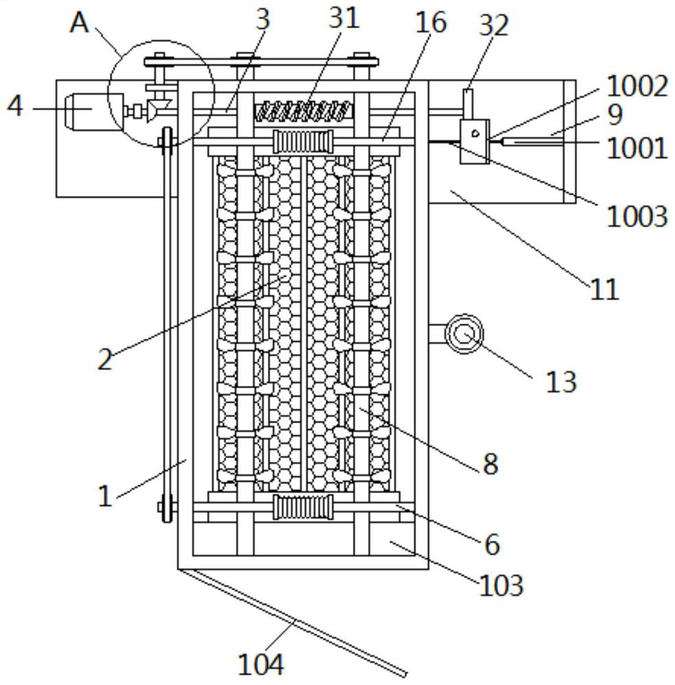
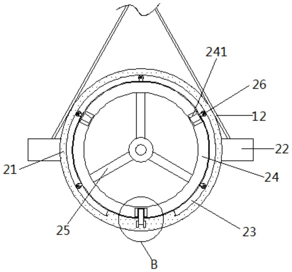
[0033] as attached figure 1 To attach Figure 10 Shown: a wood drying anticorrosion treatment device, including a box body 1, a loading device 2, a loading device 2 is installed between the left and right sides inside the box body 1, and steel bars are fixedly connected between the left and right sides of the front and rear ends of the loading device 2 Rope 12, the inside of the box body 1 is located at the front and rear sides of the top of the loading device 2, and the upper ends are respectively horizontally rotated and connected to the No. 1 retracting device 6 and the No. 2 retracting device 16. The No. 1 retracting device 6 and the No. The steel rope 12 at the front and rear ends of the device 2 is fixedly connected, and the inside of the box body 1 is located at the upper end of the rear side of the loading device 2. The left and right ends of the center between the front and rear sides of the retracting device 6 and the No. 2 retracting device 16 are longitudinally ro...
PUM
 Abstract
Description
Claims
Application Information
PatSnap Eureka turns technology decisions into work you can execute. Powered by our Innovation Knowledge Graph, it runs expert workflows across engineering, life sciences, materials and intellectual property. Get your review-ready output in minutes.


