In-situ inspection method and device for leakage of condenser heat exchange tube

A technology for condensers and heat exchange tubes, applied in steam/steam condensers, by detecting the appearance of fluid at leak points, lighting and heating equipment, etc., it can solve the problem of incorrect diagnostic results of condenser leak detection and the number of sampling points less, long measurement lag time, etc., to avoid cross-contamination of water samples, strong representativeness, and simple system

Active Publication Date: 2021-03-12
XIAN THERMAL POWER RES INST CO LTD
View PDF7 Cites 3 Cited by
  • Summary
  • Abstract
  • Description
  • Claims
  • Application Information

AI Technical Summary

Problems solved by technology

[0005] In order to solve the problem of long lag time in condenser leakage measurement in the prior art, the purpose of the present invention is to provide a method and device for in-situ inspection of condenser heat exchange tube leakage, which fundamentally solves the problem caused by the number of sampling points. Few, remote detection, etc. lead to incorrect diagnosis results of condenser leak detection

Method used


Image

  • In-situ inspection method and device for leakage of condenser heat exchange tube
  • In-situ inspection method and device for leakage of condenser heat exchange tube
  • In-situ inspection method and device for leakage of condenser heat exchange tube

Examples


Embodiment

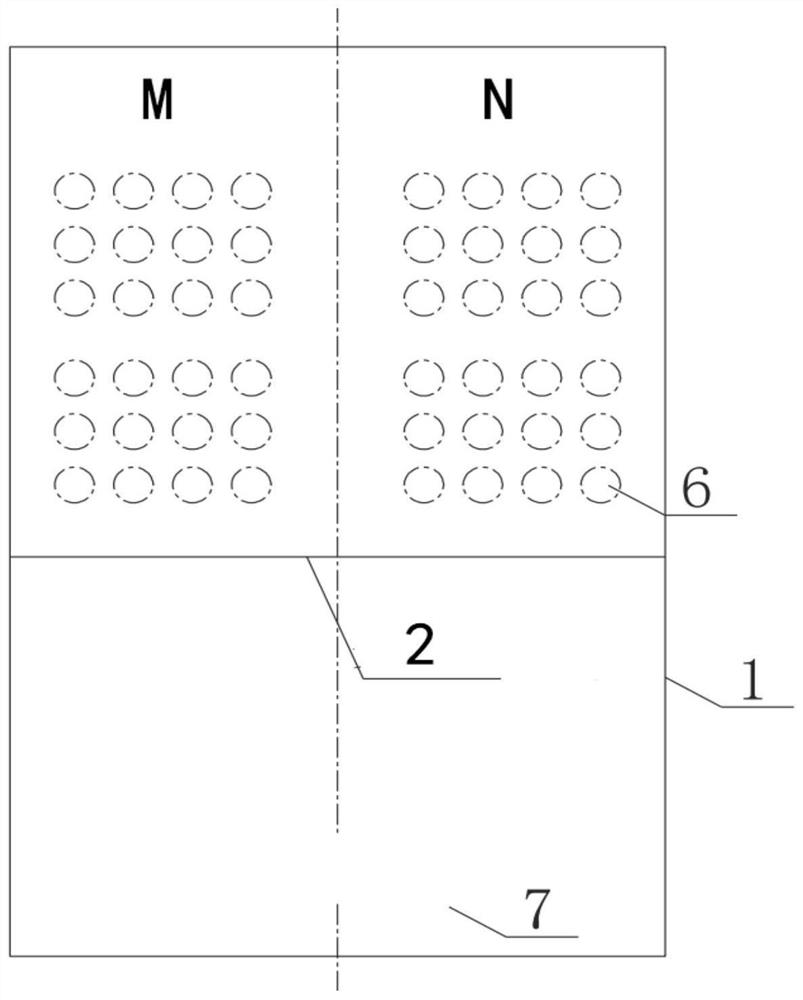
[0047] as attached figure 1 , the guide rail 2 inside the condenser 1 and the inspection vehicle 3 are located below the condenser tube 6 and above the hot well 7 at the bottom of the condenser. The exhaust steam from the steam turbine is condensed through the condenser tube 2 in the condenser 1. When the condensed water drops to the hot well 7 at the bottom of the condenser, condensed water from different positions continuously enters the inspection vehicle 3 for testing.

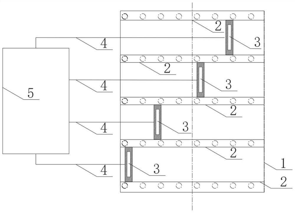
[0048] as attached figure 2 A guide rail 2 is laid above the hot well 7 at the bottom of the condenser, and the two ends of the inspection vehicle 3 are mounted on the guide rail 2. The power and control system 5 provides power and control to the inspection vehicle 3 through the control line 4. Each water chamber of the condenser 1 is arranged with several guide rails 2 and inspection vehicles 3 along the vertical length direction of the condenser tube 6, and the inspection vehicle 3 reciprocates on the ...


PUM


Abstract

The invention discloses an in-situ inspection method and device for leakage of a condenser heat exchange tube. The device comprises a condenser, a guide rail, an inspection vehicle, a control line, apower and control system, a condenser tube and a condenser hot well; the guide rail is installed above the hot well at the bottom of the condenser; the two ends of the inspection vehicle are erected on the guide rail; the output end of the control line is connected with the inspection vehicle; and the input end of the control line is connected with the power and control system. Condensed water falls into a specially-made condensed water collection device; effluent of the condensed water collection device automatically flows into a conductivity monitoring device; and the conductivity monitoringdevice is provided with a wireless communication module, so that remote transmission of a test result can be implemented. The device radically solves the problem that the condenser leak detection diagnosis result is wrong due to the small number of sampling points, remote detection and the like.

Description

technical field [0001] The invention relates to the technical field of power generation, in particular to an in-situ patrol inspection method and device for heat exchange tube leakage of a condenser. Background technique [0002] According to statistical data, about 30% of the corrosion damage accidents of large boilers are caused by the corrosion damage of condenser tubes. The direct damage of condenser tube damage is not only the loss of the condenser itself, but also the more important , due to the high quality requirements of feed water for large boilers, the water quality buffer is small, so once the condenser tube leaks, the cooling water leaks into the condensed water, resulting in an increase in the salt content of the condensed water, the main component of which is Ca 2+ , Mg 2+ 、Na + , Fe 3+ 、HCO 3 - , SO 4 2- , Cl - , NO 3 - , silicon dioxide, organic impurities, and dissolved oxygen, etc. These impurities are the main causes of fouling and corrosion of ...

Claims


Application Information

Patent Timeline
Patent Type & Authority Applications(China)
IPC IPC(8): F28B11/00G01M3/18G01N27/06
CPCF28B11/00G01M3/18G01N27/06
Inventor 李俊菀张维科龙国军孟龙胡振华汪思华王园园李健博
Owner XIAN THERMAL POWER RES INST CO LTD
Why Eureka
Try Eureka