Device and method for measuring strain tensor of two-dimensional material based on optical third harmonic generation

A two-dimensional material and strain tensor technology, applied in the field of spectroscopy and optoelectronics, can solve problems such as center inversion breaking, and achieve fast measurement speed

Active Publication Date: 2019-06-14
PEKING UNIV
View PDF8 Cites 3 Cited by
  • Summary
  • Abstract
  • Description
  • Claims
  • Application Information

AI Technical Summary

Problems solved by technology

For example, fluorescence spectroscopy is only applicable to semiconductor materials with direct bandgap and radiative transitions; Raman spectroscopy is only appli

Method used


Image

  • Device and method for measuring strain tensor of two-dimensional material based on optical third harmonic generation
  • Device and method for measuring strain tensor of two-dimensional material based on optical third harmonic generation
  • Device and method for measuring strain tensor of two-dimensional material based on optical third harmonic generation

Examples


Embodiment 1

[0024] The measurement of the local strain tensor in single-layer tungsten disulfide by optical triple frequency includes the following steps:

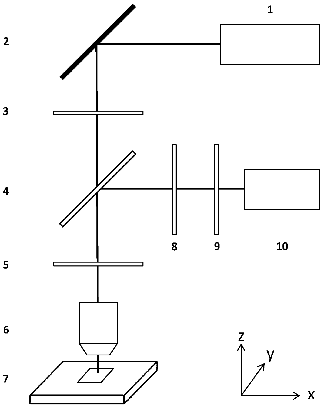
[0025] 1) if figure 1 As shown, the optical path includes a pulsed laser light source 1, a mirror 2, a first polarizer 3, a beam splitter 4, a 1 / 2 wave plate 5, a lens 6, a two-dimensional sample to be measured 7, a second polarizer 8, a filter Sheet 9, spectrometer 10. Among them, the pulse laser light source 1 has a wavelength of 1288nm, and the two-dimensional material sample to be tested is a single-layer tungsten disulfide.

[0026] Along the light emitting direction of the light source, the light source, the reflector, the first polarizer, the 1 / 2 wave plate, the beam splitter, the lens, and the measured two-dimensional material sample And its substrate, the lens, the beam splitter, the filter, the second polarizer, and the spectrometer are set in sequence.

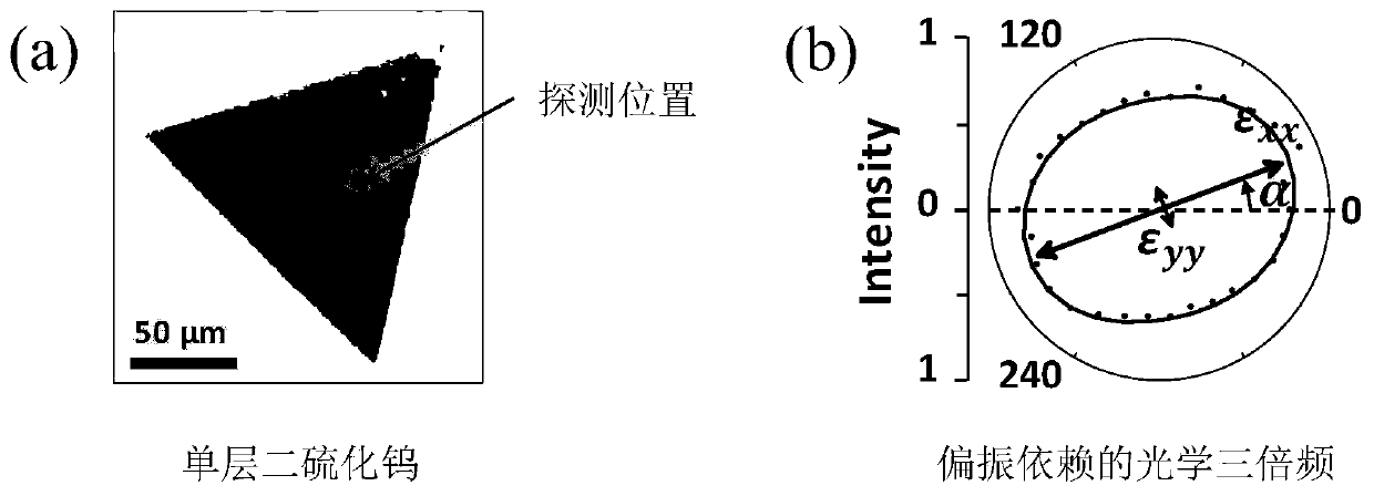
[0027] 2) At the focal point of the lens 6, place a single layer of...

Embodiment 2

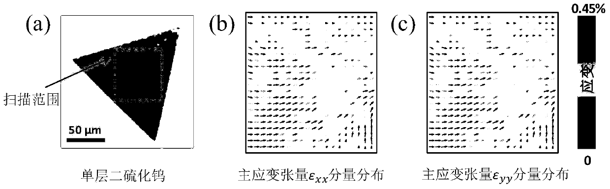
[0039] The measurement of the strain tensor distribution in the monolayer tungsten disulfide by optical triple frequency includes the following steps:

[0040] 1) if figure 1 As shown, the optical path includes a pulsed laser light source 1, a mirror 2, a first polarizer 3, a beam splitter 4, a 1 / 2 wave plate 5, a lens 6, a two-dimensional sample to be measured 7, a second polarizer 8, a filter Sheet 9, spectrometer 10. Among them, the pulsed laser light source 1 has a wavelength of 1288nm, and the two-dimensional material sample to be measured is a single-layer tungsten disulfide, which is placed on a two-dimensional piezoelectric displacement platform.

[0041] Along the light emitting direction of the light source, the light source, the reflector, the first polarizer, the 1 / 2 wave plate, the beam splitter, the lens, and the measured two-dimensional material sample And its substrate, the lens, the beam splitter, the second polarizer, the filter, and the spectrometer are se...


PUM


Abstract

The invention provides a device and a method for measuring a strain tensor of a two-dimensional material based on optical third harmonic generation. The device comprises a pulsed laser light source, areflecting mirror, a first polarizer, a beam splitter mirror, a 1/2 wave plate, a lens, a measured two-dimensional sample, a light filter, a second polarizer and a spectrograph. The device realizes the measurement of the strain tensor of the two-dimensional material, and has the characteristics of high measurement speed, simplicity and effectiveness, and no damage to the measured sample. The strain tensor measurement which is not limited by a two-dimensional material system (an energy band structure, crystal symmetry and the like) is realized for the first time; and a great help is provided for accurately regulating and controlling the performance of the two-dimensional material in the strain engineering to meet the requirements of application of the two-dimensional material to the fieldsof optics, electrics, optoelectronic devices and the like.

Description

technical field [0001] The invention belongs to the technical fields of spectroscopy and optoelectronics, and relates to a device and method for measuring strain tensor in two-dimensional materials based on optical triple frequency. Background technique [0002] Two-dimensional materials refer to materials with one dimension in nanometer size (size less than 100 nanometers), such as nanofilms, superlattices, quantum wells, etc. Strain refers to the local relative deformation of an object under the action of factors such as external force and non-uniform temperature field. Compared with traditional three-dimensional materials, two-dimensional materials have ultra-high strength and ultra-flexibility, which allows strain to more effectively regulate their electronic band structure, chemical reactivity, phase state, etc. To achieve precise performance tuning, precise monitoring of strain (magnitude and direction) is important. Spectroscopy detection methods usually have the ad...

Claims


Application Information

Patent Timeline
IPC IPC(8): G01B11/16
Inventor 刘开辉梁晶俞大鹏
Owner PEKING UNIV
Why Eureka
Try Eureka