
Control system for edge banding machine

A control system and edge banding machine technology, applied in the field of control systems

Pending Publication Date: 2021-03-12
SCM GRP
View PDF12 Cites 0 Cited by
  • Summary
  • Abstract
  • Description
  • Claims
  • Application Information

AI Technical Summary

Problems solved by technology

Another disadvantage of the above solutions is that it is necessary to use a processor with high computing power, which allows to carry out the combination and processing of the images

Method used


Image

  • Control system for edge banding machine
  • Control system for edge banding machine
  • Control system for edge banding machine

Examples


Embodiment Construction

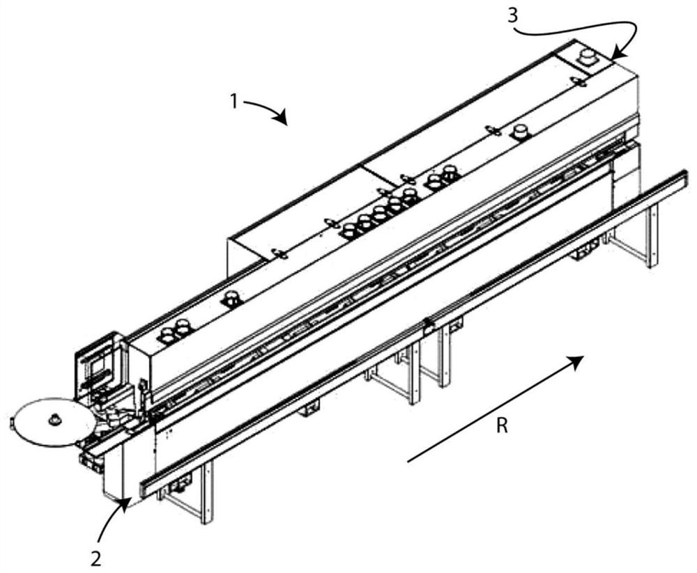
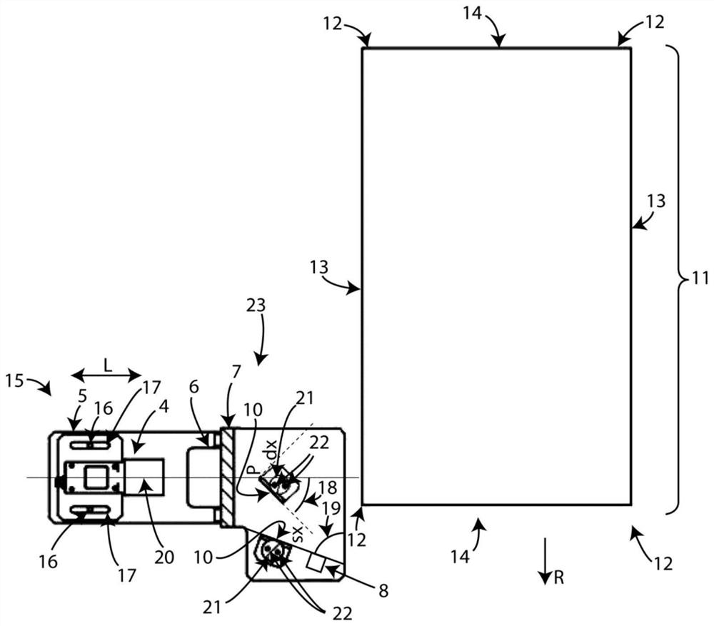
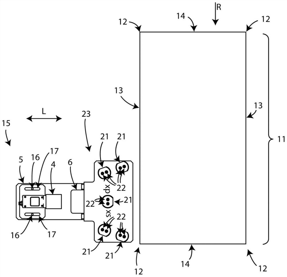
[0052] With reference to the above-mentioned figures, the control system 15 of the invention for an edge banding machine 1 comprises a system with a camera 4 (with its optics) and at least two mirrors 10 for converting the desired image (in this case images of the head and tail edges of the board 11 ) are reflected towards the camera 4 belonging to the above-mentioned system 15 .

[0053] The control system 15 for the edge banding machine 1 is preferably located at ( figure 1 ) in the empty compartment 3 downstream of the edge banding machine 1, the panels to be striped 11 ( Figure 2-6 , 8-9) along the edge banding machine 1 through the support roller conveyor 2 along Figure 1-9 R slide in the longitudinal direction.

[0054] The illustrated sheet 11 has two side surfaces 13 ( figure 2 ), which corresponds to the longer side of the sheet 11 itself; perpendicular to the side surface 13 and parallel to each other and opposite to each other, there are two side surfaces 14, ...


PUM


Abstract

The present invention relates to a control system (15) for an edge banding machine (1). The control system includes a camera (4) with a relative observation cone and is used to reflect a light beam (F) from the camera (4) to two inclined mirrors (10) on a vertical edge (12) belonging to a plate (11).

Description

technical field [0001] The invention relates to a control system for an edge banding machine that allows inspection of the vertical edges of panels made of wood or similar material. [0002] Thus, the invention is in the field of machines suitable for controlling the quality of sheets plus strips. Background technique [0003] Implementing a quality control system for parts machined by edge banders is currently a matter of note. In fact, these quality control systems are difficult to implement in this technical field due to various and different constraints, such as those of physical and structural type. The edging process of wood particleboard panels is designed to cover the sides of a previously cut panel with a finished edge by an applied glue. The edges applied at the perspective of the side section of the panel should be as true as possible to the nature of the main surface of the panel, or aesthetically matched thereto. The edge banding machine is a machine that per...

Claims


Application Information

Patent Timeline
Patent Type & Authority Applications(China)
IPC IPC(8): G01B11/02G01B11/04G01B11/06B27N7/00
CPCG01B11/022G01B11/043G01B11/0691B27N7/00B27D5/003G01N21/8986
Inventor 乔利·马蒂亚
Owner SCM GRP
Learn More