Check patentability & draft patents in minutes with Patsnap Eureka AI!

Sapphire wafer positioning and tracking method based on circle detection

A sapphire wafer, positioning and tracking technology, applied in the field of visual positioning, can solve problems such as low efficiency and easy statistical errors, and achieve the effects of avoiding measurement steps, low error rate, and high efficiency

Active Publication Date: 2021-03-12
HANGZHOU ZHONGWEI PHOTOELECTRICITY
View PDF10 Cites 2 Cited by
  • Summary
  • Abstract
  • Description
  • Claims
  • Application Information

AI Technical Summary

Problems solved by technology

[0002] Existing sapphire wafer thickness detection is done manually, using sensors to measure the thickness of each sapphire wafer on the ceramic plate, and then manually recording the data in the form, which is inefficient and prone to statistical errors

Method used


Image

  • Sapphire wafer positioning and tracking method based on circle detection
  • Sapphire wafer positioning and tracking method based on circle detection
  • Sapphire wafer positioning and tracking method based on circle detection

Examples


Embodiment 1

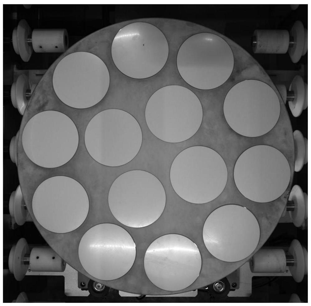
[0068]Such asfigure 1 As shown, the present invention is based on a circular detection of sapphire wafer positioning tracking objects as a ceramic disk and an interior of the internal 4 tablets above the outside.

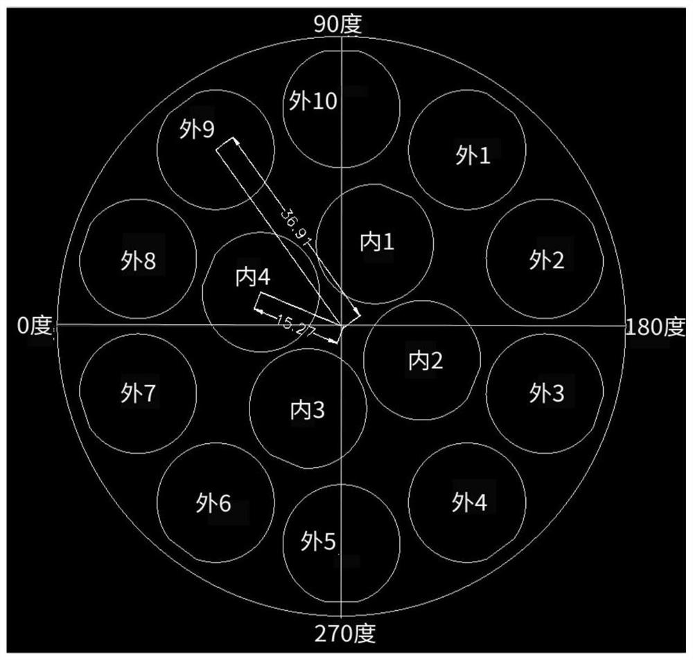
[0069]figure 2 The sequential diagram of a sapphire wafer positioning tracking and sapphire sheet is shown in the present invention.

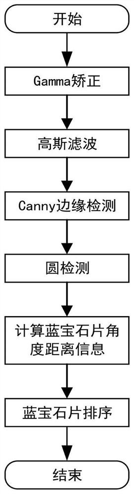
[0070]image 3 The flow chart showing the positioning tracking algorithm based on a round-detected sapphire wafer based on a circular detection.

[0071]Figure 4 The present invention is shown as a circularly detected sapphire wafer positioning tracking method, including: S01, calibration: acquisition single calibration board image and corresponding robot end clamp position information for calibration, to obtain a camera coordinate system and robot coordinate system Relationship matrix;

[0072]The specific steps of S01 are:

[0073]S01-1, mounting the industrial camera on the bracket above the ceramic dish, ensuring that the ceramic disk image can be tra...


PUM


Abstract

The invention discloses a sapphire wafer positioning and tracking method based on circle detection. The sapphire wafer positioning and tracking method sequentially comprises the following steps of: (1) collecting a single calibration plate image and the position information of a corresponding robot tail end clamp for calibration, so as to obtain a relation matrix between a camera coordinate systemand a robot coordinate system; (2) collecting a single ceramic disc image and processing the single ceramic disc image by means of a visual detection system, and detecting all sapphire wafers and ceramic discs; (3) calculating to obtain the number, positions and angle information of the sapphire wafers by means of the visual detection system; and (4) acquiring position information of the sapphirewafer under a robot coordinate system through coordinate transformation, realizing positioning of the sapphire wafer by the robot, and then performing accurate thickness measurement. The sapphire wafer positioning and tracking method combines visual positioning and automatic measurement, achieves automatic detection of the thickness of the sapphire wafer, and has high flexibility.

Description

Technical field[0001]The present invention belongs to the field of visual positioning, and is specifically involved in a circularly detected sapphire wafer positioning tracking method.Background technique[0002]The existing sapphire wafer thickness detection is performed by manual, using the sensor to measure the thickness of each sapphire wafer on the ceramic disc, and then manually record data in the table, and the efficiency is low, and it is easy to statistically errors. In this context, it is proposed to achieve positioning detection by means of automation and visual positioning technology, thereby increasing the degree of automation of the factory, reducing labor costs and labor intensity. The main functions of the visual inspection system include: 1, identify the two-dimensional code on the back of the ceramic disc, for the positioning angle, perform sapphire wafer sorting; 2. Detect the sapphire wafer position on each model ceramic disk, and send it to the robot to position. ...

Claims


Application Information

Patent Timeline
IPC IPC(8): G01B21/08G01B11/00G01B11/26
CPCG01B21/08G01B11/002G01B11/26Y02P90/02
Inventor 刘华胡贤波叶欣何守龙
Owner HANGZHOU ZHONGWEI PHOTOELECTRICITY
Features
  • R&D
  • Intellectual Property
  • Life Sciences
  • Materials
  • Tech Scout
  • Unparalleled Data Quality
  • Higher Quality Content
  • 60% Fewer Hallucinations
Learn More